Other Parts Discussed in Thread: LM239, , LM239A
Tool/software:
Hi Team,
Recently we sent the PCN for LM339: LM239ADR_Rbull_PCN_20231219002_1_Change_Notification.docLM239DR_PCN20231016006.1_Change_Notification.docLM339DR_PCN20231016006.1_Change_Notification.doc. ctm is testing the post-PCN device to see whether the PCN will influence their design. To help their test, could you please help to review below sch and provide the suggestion on whether these sch will be influenced by PCN?
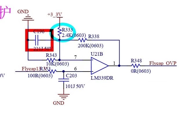
sch1:
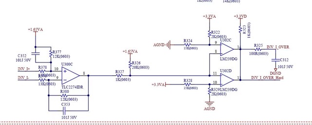
sch2:
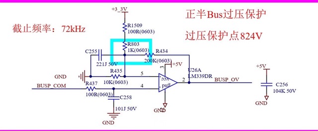
sch3:
BRs,
Rannie