Tool/software:
I have a circuit using a INA193 to sense the current through a 60m ohm sense resistor. My sense supply is +/-15V. My INA193 supply is 7V. Both + and - circuits are identical except where the +IN and -IN on the negative rail are connected in reverse. The +IN on both are the high side.
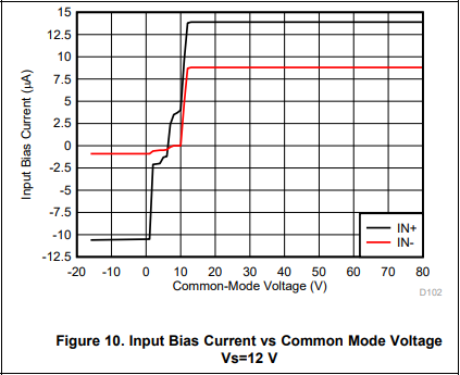
It appears that the input bias current for +IN is higher than the stated datasheet values for the +15 rail. I have an input filter using matching 100ohm resistors per the datasheet. The resistor on the +IN for +15V drops1.7mv, while the resistor on -IN drops 0.7mv. Both resistors on the +IN and -IN pins for the negative rail drop close to the same value at around 1.0mV and 1.2mV respectively.
A 350mA load on both +15 and -15 create different results from the two INA193's. I can only assume this difference is due to the additional drop in the bias currents.
I have removed the filter resistors on the + Rail and the results between the two INA193's match.
Isense: Both match
Vsense: Both match
My question is, why are the two INA193's yielding different results when they are connected similarly and have identical currents through the sense resistor and is there a way to make them match with the filtering network?


