- Ask a related questionWhat is a related question?A related question is a question created from another question. When the related question is created, it will be automatically linked to the original question.
This thread has been locked.
If you have a related question, please click the "Ask a related question" button in the top right corner. The newly created question will be automatically linked to this question.
Tool/software:
Hello,
I am designing the Power Monitoring Device for AC220V. In the voltage measuring part,
I need isolation. So, I want to use AMC1200, a device for a fully Differential Isolation Amplifier.
But I am new to this IC, so I don't know if my design is correct.
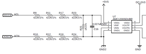
The following is the schematic for the AMC1200 part.
I would appreciate it if you could tell me whether it is correct or not.

Thanks,
Hi Seogje,
In general this is correct, but it is important to note that all the high side VDD1 supply must be referenced to GND1 (GND2 net) which is in the mid point of the resistor divider.
Is this for a single or 3 phase voltage measurement?
To simplify the design, you could consider a device such as AMC3301 with integrated DC/DC converter.
Hi! Alexander,
Thanks for your reply.
My design is for the single-phase AC220V voltage measurement.
I have changed the schematic as follows.

I am attaching the power supply for the ACM1200.

I have two concerns.
One is that this schematic is immune to that if the user swaps between ACL and ACN Lines. The Other is that the output of AMC1200 is shifted above the zero point.
Am I right?
Hi Seogje,
I see, I think your implementation is a clever way to handle swaps between ACL and ACN. This is OK for the AMC. I cannot comment for the U2.
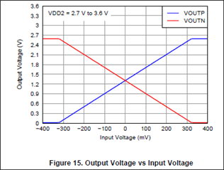
The output will be shifted above the zero point, this is the common-mode output voltage.
You can also see the input to output voltage relationship by the figure I've pasted below from the datasheet.
VOUTN should not be directly connected to GND2 however. This is a driven output. Please add a 10kohm resistor between VOUTN and GND2 if you do not wish to use the differential output. Otherwise the device may be damaged.

Hi Alexander,
Thanks for your assistance.
I will implement the circuit.
Thanks again.