This thread has been locked.

If you have a related question, please click the "Ask a related question" button in the top right corner. The newly created question will be automatically linked to this question.

INA186: Negative current Measurement

Part Number: INA186
Other Parts Discussed in Thread: INA230, INA169

Tool/software:

Hello TI Team,

We are planning to use INA186 amplifier for current measurement of -24VDC@1A supply.  

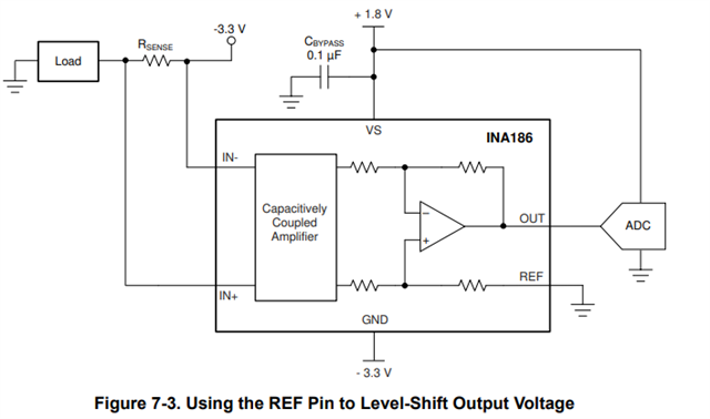
As per the attached datasheet reference image, INA186 is used for the -3.3V voltage current measurement. So based on that reference image we have below queries:

1. Can we use same reference circuit for the -24VDC@1A current measurement?

2. Can we connect GND pin with -24VDC?

3. What will be the REF pin status when we want to measure the negative voltage?

4. As per the datasheet common-mode voltage mentioned as positive, then for the -24VDC will it work?

Kindly consider digital supply as +3.3VDC.

If above chipset is not workable solution, then kindly suggest the other solution to measure the -24VDC@1A supply.

Regards,

Parth
  • Hi Parth,

    Technically the reference diagram above could be used if the Vcm is within range and Vs and GND don't exceed 5.5V - as mentioned in the paragraph below.

    However, if you set GND and supply at -24V, the Vcm would be within range but then your Vs would exceed specs. To satisfy the 5.5V requirement, you could lower your Vs to -18.5V, but its going to be difficult to set these arbitrary negative voltages and is not recommended.

    Instead, I'd recommend:

    1. Floating your INA186's GND using a Zener diode

    2. Using an isolator circuit on the output

    3. Level shifting circuit on the output side

    If you'd prefer a more integrated solution, I'd recommend our digital device portfolio (e.g INA230) or TMCS devices.
    Please refer to the following E2E thread for more information on this;
    https://e2e.ti.com/support/amplifiers-group/amplifiers/f/amplifiers-forum/1416619/ina230-negative-voltage-sense-and-negative-current-measure

    Best,
    Mallika Senthil

  • Hello Mallika,


    Thank you for the suggestions. As we don't have any I2C interface to measure the output voltage, suggested solution may not suitable for our design.

    Mean time, we have found the below TI document for measure the negative current.

    TI Document Link: https://www.ti.com/lit/an/sboa595/sboa595.pdf?ts=1727176638624&ref_url=https%253A%252F%252Fwww.google.com%252F


    Based on the above document we have below queries:

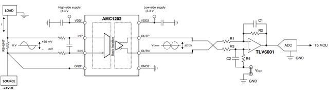
    1. Current Sensing Based Isolated Amplifier:

    - Will isolated amplifier circuit work for measure the -24VDC@1A supply?

    - We don't have any isolated sensing requirement, Can we provide the same digital supply on both the side of the amplifier (VDD1 and VDD2)?

    - If the provided VDD supply on both side (VDD1 and VDD2 = 3.3VDC) and sense supply (-24VDC) is different then will these solution will work?

    - Do you see any input common mode voltage related issue, if we use these current measurement solution?


     2. Negative Power Supply Current Sensing Based Current Sensing Amplifier:

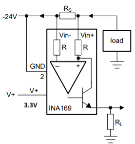
    - As per the attached reference image, will INA169 work to measure the negative supply current measurement?

    - Do you see any input common mode voltage related issue, if we use INA169 for -24VDC current measurement?

    - Our supply voltage V+ is 3.3VDC and we have provided -24VDC as GND for negative current sensing also output voltage will refer to the 3.3VDC supply. Will these solution work?

    Regards,

    Parth 

  • Hi Parth,

    Will isolated amplifier circuit work for measure the -24VDC@1A supply?

    Yes our AMC series of isolated amplifiers will work.

    We don't have any isolated sensing requirement, Can we provide the same digital supply on both the side of the amplifier (VDD1 and VDD2)?

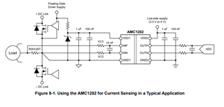
    No, you can't have the same supply on both VDD1 and VDD2 since the two supplies have different grounds; -24V and 0V. You must isolate your supplies since the grounds are separate, and you can do this using Zener diodes. Please see figure 8.1 below, its shows you how the 2 supplies are floated using regulators. 

    Do you see any input common mode voltage related issue, if we use these current measurement solution?

    We don't spec our device performance at this voltage so I can not say for sure. The AMC product line may have more details, I suggest creating a new E2E thread for that team.

    As per the attached reference image, will INA169 work to measure the negative supply current measurement?

    The INA169 is used to measure negative supply, but at High side applications. Your intended application appears to be low side so it will rail the device and break it.

    Best,
    Mallika Senthil

  • Hello Mallika,

    Thank you for the feedback.

    2. Negative Power Supply Current Sensing Based Current Sensing Amplifier:

    As per the above reference document, we are planning to use the same reference circuit of INA169 to measure the -24VDC current. Could you please elaborate more, why our applications seems low side sensing?

    Regards,

    Parth Kalaria


  • Hi Parth,

    The diagram in the reference document needs to be revised, I've reached out to the team.
    The reason I said the diagram in reference document won't work is because if you look at the output section, there is transistor output leading to GND via a resistor. The voltage at the transistor must be higher than the GND, but if we connect a -24V supply, the direction of current is going to be reversed and the transistor will not function.

    For your application, to make the circuit work, I suggest moving the load to the other side of Rs and connecting Rs to V+; as shown in the diagram below.

    Best,
    Mallika Senthil