THS4521: Noise issue in differential signals

Part Number: THS4521
Other Parts Discussed in Thread: OPA2992, THS4551

Tool/software:

Dear TI expert,

We are using THS4521 for converting single-ended to differential signal. Differential signals are going out of the board via ethernet cable to MCU ADC on the other board.

    - MCU ADC configuration is in differential mode. But ADC output is having too much variation.

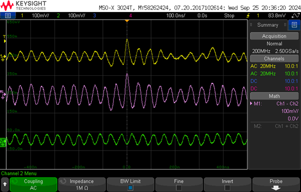
    - On further testing with oscilloscope, without connecting the controller board, signals look much clean but as soon as the controller board is connected differential signals become bad. Especially the signal named Ia_sen_P, in picture below. Ia_sen_N is relatively very good.

Please suggest.
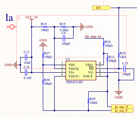
Regards,

Jitendra

  • Hi Jitendra,

    Thank you for sharing the debug steps you have taken. It does seem like there is some kind of reflection or something along those lines because you shared the signals actually looking good when probing directly at the output of the FDA. Could you share how you set up the circuit beyond Ia_sen_N and Ia_sen_P? Did you have some kind of termination circuitry on the other end of the ethernet cable? Improper impedance matching can result in almost random signals being measured by the ADC. 

    Best Regards,

    Ignacio

  • Dear Ignacio,

    Thanks for the suggestions. Please find more details of the setup below

    Also the capture of the scope of n and p signals is below (yellow: Ia_sen_P, green: Ia_sen_N). Both signals are captured near the THS4521 outputs:

    Can you point out the procedure for impedance matching for this setup?

    Regards,

    Jitendra

  • Hello Jitendra,

      Ignacio is out, and will be back to the office soon. In the meantime, I can answer your question. 

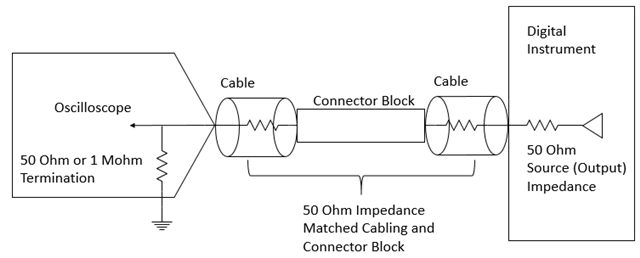
      Impedance matching especially with long cables, depending on the input frequency, can cause power reflections which is what you are seeing. Here is the proper procedure for impedance matching for your setup:

       Also, make sure your traces have 50-ohm impedance. This ensures 50 ohm matching since the cables you are using in the setup are also 50 ohm impedance for industry standards, or 100 ohm differential impedance. Here is a third party source showing this 

    Thank you,

    Sima

  • Dear Sima,

    Thanks for the suggestions.

        - Input of THS is from OPA2992. Do I need to consider the output impedance of OPA2992, which varies with the frequency, to calculate Rf and Rg values.

        - Application notes suggest to choose Rf < 1k, what would be the good value.

        - You suggested 50 ohm diff, near MCU. To match 100 ohm differential impedance of ethernet cable, should it be 100 ohms.

    Regards,

    Jitendra

  • Hi Jitendra,

    If the OPA2992 is designed on the same PCB and is relatively close to the FDA, I do not think it requires impedance matching especially when you consider the speed of the signals coming from the OPA2992. That is a good catch with the feedback resistor value. We do recommend sticking with a feedback resistor in the 1kohm range and adjusting Rg accordingly. For the question regarding the differential impedance, you are correct the 50ohm was a typo. One suggestion would be to slightly adjust the values given, to increase the load the FDA will see. By increasing the load seen by the FDA, you will get better distortion performance. An example is shown below. This will match the differential impedance looking the towards the MCU while also providing a larger load to the FDA, improving distortion performance.

    Best Regards,

    Ignacio

  • Dear Ignacio,

    Thanks for the reply and the suggestions.

    I've few more questions:

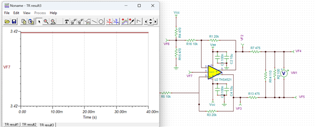
    1. If we leave the Vocm pin unconnected, what is the expected voltage. In TINA, it is showing 3.42V, refer pic 1.

    2. Is it ok to drive the Vocm externally with resistor divider which is causing the swing of 40mV/50Hz in Vocm due to loading on resistor divider.

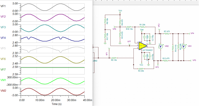
    3. Why there is a dip in VF4 and VF5, refer pic 2.

    4. Differential output voltage swing, VM1, required at ADC is -2.5V to +2.5V which doesn't look possible with the suggested resistors combination. It is coming -240mV to +240 mV, refer pic 2. What are the other options.

        - Is it ok keep 50 ohms resistors in series as earlier while shifting parallel resistor directly between THS outputs to increase the load of THS. Impedance will be matched and load on FDA would increase.

    5. In the current design, it is not possible to decrease Rf and Rg otherwise it is causing too much swing in Vocm.


    Please provide your suggestions on all the points above. I've also attached the tsc file for your review.Jit_16_10_2024_1341.tsc

    Regards,

    Jitendra


  • Hi Jitendra,

    By leaving the Vocm pin floating the voltage to default to mid supply, meaning 2.5V in this case. The model is likely structured wrong internally which is why it is showing you this 3.42V bias. For this pin you can definitely bias the pin externally using a voltage divider like you suggested however if you will be biasing to mid supply, it is more convenient to let the internal bias circuitry bias the circuit. All that would be suggested would be to add a 1uF capacitor from that Vocm pin to ground as this reduces noise in the circuit. The dip you see is likely an artifact of the model. I was able to simulate the circuit with the THS4551, a device very close in specs to the THS4521 and did not find this dip. The THS4551 model would be worth considering for simulations as it seems to be capturing the real-life device more accurately. I also agree the suggestion made will cause an attenuation and result in a limited full-scale range into the ADC. You can keep the 50-ohms series terminated with the 100ohm differential as this would still match, however distortion will increase as you will be loading the device. For the last question could you explain what you mean by causing too much swing in Vocm?

    Best Regards,

    Ignacio

  • Dear Ignacio,

    Thanks.

    I've two more questions related to this design:

        - In addition to differential mode impedance matching, is it required to do common mode impedance matching

        - What is the recommended value of R3, in pic below, to get the optimum performance

    Regards,

    Jitendra

  • Hi Jitendra,

    Differential impedance matching would be the concern in this design as you are measuring and capturing a differential signal. I am not sure common mode impedance matching applies here. The R3 resistor would be loading the device even more. The ideal configuration would be with the R3 removed as it will still be matching and will give the device a higher load.

    Best Regards,

    Ignacio