This thread has been locked.

If you have a related question, please click the "Ask a related question" button in the top right corner. The newly created question will be automatically linked to this question.

INA296B-Q1: INA296B4Q - Gain Error Factor

Other Parts Discussed in Thread: INA240

Tool/software:

Hi,

Based on the feedback from e2e forum for the query, "INA296B4Q - Gain Error Factor",

  • To calculate the gain error factor for the use case of an external series filter resistor (Rs), it has been suggested to make use of the following formula.


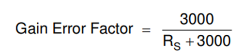
  • Formula mentioned here is suitable for INA240 devices

  • 3000 needs to be replaced as 3250 for INA296 devices.

Could you please provide more details about the parameters on which the value i,e, 3250 has been estimated for the INA296 device?

  • Hello Devendhiran,

    This has to do with the input impedance or the INA296 being different than the INA240.  This is just an estimate and we normally recommend smaller than 10Ω at the inputs.  The value will change as the input impedance value could change from device to device.

    Regards,

    Javier

  • Hi Javier,

    Thanks for the feedback.

    With respect to the input bias current of INA296Bx device, the input impedance is approximated to 28.5K ohm (for VCM=1V) to 3.14Mega Ohm (for VCM= 110V) range.

    In this condition, how we can consider the 3250 Ohm as an Input impedance approximation for the INA296 CSA.

    Could you please provide a more insight about this value determination?

    Regards,

    Devendhiran K

  • Hello Devendhiran,

    I would not consider the input an impedance but rather a current required independent of the VCM range.  This is explained in the video I shared previously in another thread:  https://www.ti.com/video/6219017476001.  This cover the VCM IB and VSENSE IB.  Gain error is impacted by the IB vs Vsense and that is where the 3250Ω comes from and not the VCM impedance you are looking at in your above.

    IB vs VCM for INA296 you can see the IB does not change with VCM.  So this is IB source that is not really an impedance relative to VCM as it does not change with VCM.

    For IB vs Vsense you can see the IB does change with Vsense and then you can consider this a differential impedance.  One pin does have a little more current at Vsense = 0.  This is very small as it does not look like it in the plot.