This thread has been locked.

If you have a related question, please click the "Ask a related question" button in the top right corner. The newly created question will be automatically linked to this question.

OPA627: Operational amplifiers fail the electrical test. Parts with the designation "423XL" measure 13kOhms (NOK)

Part Number: OPA627

Tool/software:

Hello,

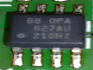
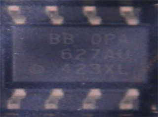
a customer claims delivered parts with P/N: OPA627AU/2K5 that carry a marking of "423XL", while parts with the marking "21GHZ" seem to be ok...

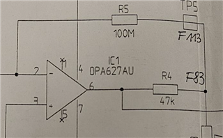
The customer purchased 300 pcs with the marking "423XL " from us. They measured 15kOhms across the R5 resistor (please see schematic), while the parts from a different source with marking "21GHz" showed a resistance of 100 MOhms across the resistor R5, which was ok...

The aprts we shipped have Date Code: 2405+5 and are from Lot#: 4084858ML4 

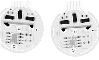
I'm also adding a provided X-Ray image of both amplifiers as comparison.

Can you please advise?

Thank you very much

Best regards
         

  • PCN 20240501000.1 made quite a lot of changes; see revision B of the datasheet.

    The schematic is incomplete; I cannot see a current path that would result in 15 kΩ.

    Is there an actual problem when trying to use the board?

  • Hello,

    Thank you Clemens, agreed.

    There has been a move to a different fab. for this device, hence the PCN and changes in the data sheet that Clemens mentioned.  However most of the specifications are the same.  I'm not sure why the resistor measurement you are trying to make would be different, but I don't think it is a direct correlation to the performance of the amplifier.  Please let us know if there is a problem with the amplifier functionality and we can look into it.

    Regards,
    Mike

  • Hello Mike,

    we are the end user in this matter. I discovered this thread by chance.
    I assume, the reason for the wrong resistance measurement is the change in input protection from 2V to 0.5V below or above the supply voltages. Due to the very high resistance of 100Meg, the measuring voltage is several volts and higher than the suppression limit after the change.
    By guarding the output pin during ICT, the measurement seems to be correct now.
    But there are some question concerning the PCN.
    Why is only a change in FAB and process indicated? As we can see on the X-ray image and with many parameter changes, it appears to be a design change. Another point is the date code 42, Feb 2024. This means that it is ahead of the PCN of May 2024 and first shipment of July 2024. This causes some uncertainty.

    Regards,
    Achim

  • Hi Achim,

    Good news regarding the measurement, thank you for letting me know.

    Most of the time, when the fab is changed, the die size is reduced.  But there are some accommodations in the design to allow for the new fab., it would be incorrect to say the internal design is exactly the same.  However the intention of the new die was to meet the same specifications, it has been fully qualified.

    Regarding the date code, we do build the initial lots and evaluate the performance before the PCN is released.  This means the manufacturing of the device can occur before the PCN date, which is why the date code would pre-date the PCN.

    Hopefully this helps answer your questions.

    Regards,
    Mike