This thread has been locked.

If you have a related question, please click the "Ask a related question" button in the top right corner. The newly created question will be automatically linked to this question.

INA228: Shunt Sense not reading a consistent 0.00mV with IN+ and IN- shorted together

Part Number: INA228
Other Parts Discussed in Thread: SYSCONFIG, INA236

Tool/software:

Hello, I'm an electronics newbie, trying to get INA228 working on my first custom board.  My goal is to measure a 12V automotive battery voltage (VBUS) and current (VShunt, mV reading across a shunt resistor, IN+ to IN-)

I'm using the Arduino INA228 library by Rob Tillart to communicate over i2c.   The VBUS register is reading as expected, but VSHUNT register is alternating between 0 and 0.33V when I have IN+ and IN- shorted together for debugging.  The 0.33V is actually 0.32768V, a number which might give a hint.

The function being used to read register address 4h is as follows:

float INA228::getShuntVoltage()
{
uint32_t value = _readRegister(INA228_SHUNT_VOLTAGE, 3);
value >>= 4;

}

I have not changed any default values in software, and the board layout looks similar to examples.

I am looking for tips on next steps for debugging.   I am not 100% certain that the library I'm using actually works, because there is a note about it being un-tested on Github.

Any advice is appreciated, thank you!

  • Missing last line from the code, sorry:

    return value * 312.5e-9;

  • Hey Mark,

    I'm not familiar with that code project, so I'm not sure exactly where the issue is. That being said, we do provide software support through SysConfig, which generates c code based on your configuration settings. It also has convenient functions for parsing register data. Here is a link to SysConfig: https://dev.ti.com/sysconfig/index.html?product=ascstudio&device=Other

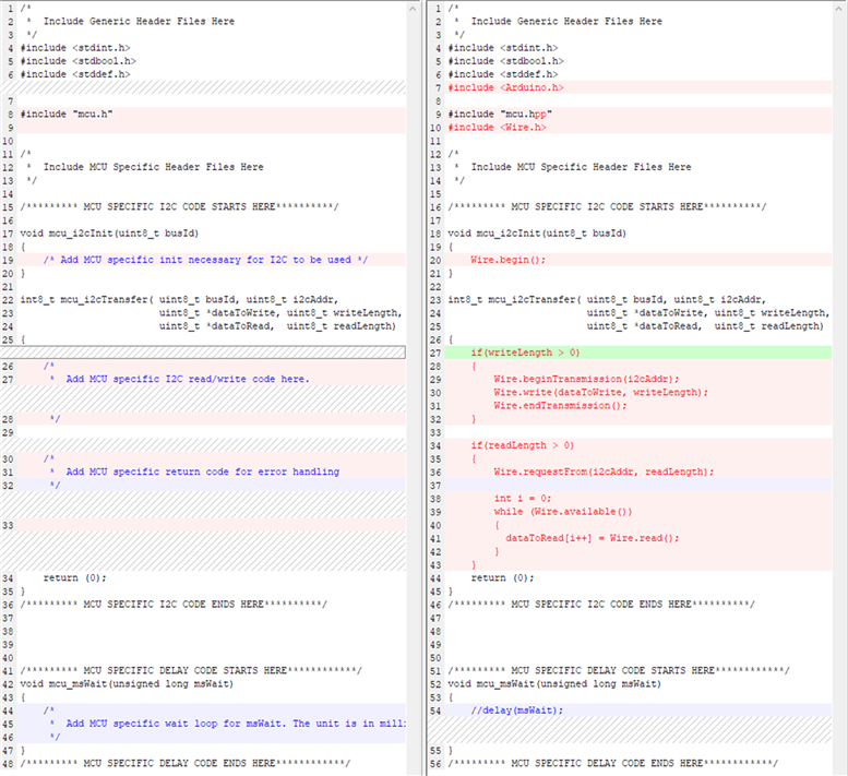
    After you use SysConfig to generate code with your desired configuration settings you can easily convert this code to Arduino code by following these instructions (this example is for the INA236, but works for any device): 

    1. Download all.zip from the ASCStudio Sysconfig project
    2. Find Arduino documents folder
    3. Create new sketchbook folder that is the same name as your main INO file
      1. Create a "main" folder sketchbook to reflect main.ino
    4. Change the main.c extension to main.ino
    5. Change the sysconfig file extensions from .c & .h to .cpp & .hpp
    6. Opening main.ino should open the entire sketchbook of files
    7. Change the #include statements at the beginning of each file to reflect the extension change (ex. #include "mcu.h" to #include "mcu.hpp")
    8. To communicate between your MCU of choice and INA236 (or any other current sensor) you'll need to add MCU-specific code to mcu.cpp. Arduino has a premade library for I2C/two-wire communication called "Wire" - here's a guide
      1. Add an include statement for the Wire library in both mcu.cpp and your main.ino
      2. Start the wire communication in the mcu_i2cInit function
      3. Add write and read code to mcu_i2cTransfer function from examples given in the Wire guide for Arduino
      4. Add delay function to mcu_msWait
        1. This also requires that you add #include <Arduino.h> in your mcu.cpp if you use delay() from the Arduino library
    9. hpp, INA236.cpp, mcu.hpp, config.cpp, and config.hpp do not require changes beyond the includes and extension changes
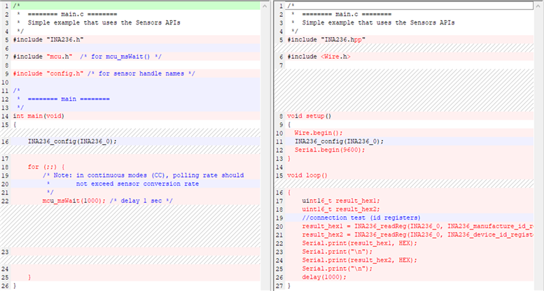
    10. Finally you'll need to write the main loops inside your main.c now main.ino file
      1. Instead of int main(void) you will have two functions void setup() and void loop() following with standard Arduino
      2. Inside void setup you'll include code to start the wire communication and serial to output the information/current you're reading to the serial monitor in the Arduino IDE. You'll also need to include the configuration function to configure the INA236_0 struct
      3. Inside void loop you will write functions that utilize your INA236.c functions for instance INA236_readReg to pull current values or manufacturing IDs
    11. From here you can compile the code and upload it to the Arduino
    12. To connect the Arduino to an INA236EVM you connect
  • Hi Mitch, thank you for your excellent and detailed response.  By looking at the generated C code, I was able to find an error in the library I was using, which did not allow for the reading of negative voltages.  Additionally, I discovered a miscommunication with the board design, result of which was that there were two shunt resistors in the circuit.  One external, which I wanted, and one internal, which was unwanted and causing many confusing results.  

    After fixing both of these issues, everything is working perfectly.  

  • Hey Mark,

    Great! Glad it is all working for you.

    Regards,

    Mitch