This thread has been locked.

If you have a related question, please click the "Ask a related question" button in the top right corner. The newly created question will be automatically linked to this question.

INA128: Adding LPF for the INA128

Part Number: INA128

Tool/software:

Hi,

I need some help on my design with INA 128.
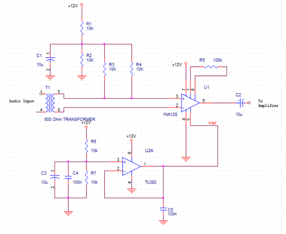
My circuit is simply an audio amplifier. It works pretty well, but I think that there is some high frequency noise at the output. Plese help me check the circuit, and let me know how to filter high frequency from the output? Can I add a capacitor paralell with R5 to make an LPF? 
Maybe using a capacitor between In+ and In- is better?
Regards

Tuan Tran
  • Tuan,

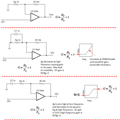
    • Don't put a capacitor in parallel with R5.  This will do the opposite of what you are hoping for.  At high frequency this will cause the gain to increase.
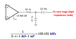
    • To limit the bandwidth, you can use a circuit like what is shown in the top figure below.  This is a simple low pass filter.  Adjust the filter capacitor (C1) to achieve your desired cutoff frequency.    
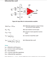
    • You could also add an input filter as is shown in the bottom figure below (also on page 53 of analog engineer's pocket reference).

    Best regards, Art

  • Hi Sir,
    Thank you for your promptly response.
    It seems to be very clear to me now. Just 2 other questions:
    - Put a capacity in parallel with R5 making it a HPF, so what if I put it inserie with R5? An LPF?
    - Is the way I bias INA 128 inputs correct? (sorry for my mistake, R4 should connect to IN- of INA 128)

    Best regards,

    Tuan Tran

  • Tran,

    1. I don't recommend adding a capacitor to the gain set resistor.  To understand the behavior of the circuit it is easier to just think of the INA input stage as an non-inverting op amp circuit.  Technically this circuit is built from two non-inverting amplifiers. Adding this capacitor can cause stability issues.
    2. Think of the capacitor as having an impedance of zero at low frequency and infinite at high frequency (Xc = 1/(2pi*f*C). 
    3. When the capacitor is in parallel with Rg the impedance of Zg will be equal to Rg at low frequency and will decrease towards zero as frequency increases.   This causes gain to increase at high frequency.
    4. When the capacitor is in series with Rg the impedance of Zg will be infinite at low frequency so the gain is 1V/V.  As frequency increases the impedance Zg will decrease causing gain to increase.  At high freqeuncy Xc will be approaxmately zero and the gain will become Rf/Rg +1.

    Best regards, Art