This thread has been locked.

If you have a related question, please click the "Ask a related question" button in the top right corner. The newly created question will be automatically linked to this question.

OPA323: Slew rate of OPA323 appears to be far less than specified 33V/µs

Part Number: OPA323
Other Parts Discussed in Thread: TLV365

Tool/software:

I’m using OPA323IDCKR as a voltage follower, powered by +/- 2.5V, input is sine wave of 2.3MHz 3.5V pk-pk, output is totally unloaded (only with 10x oscilloscope probe). As you can see, the output is slew rate limited at around 5V/µs, far less than specified.

Any ideas? This is not a special case, it happens in every case. I’m sure that power is applied and decoupled properly. When frequency drops, output turs back to normal.

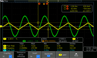
Green: input, Yellow, output. 

  • After some research, I found the application note Ramping Up on Slew Rate discussing "slew boost" in op-amps. It seems that the OPA323 may have a lower natural slew rate, and the specified 33V/µs can be achieved only under overdrive (i.e., large differential input voltage), which is not the case in the above sine wave voltage follower application.

    Can any analog experts confirm that the natural slew rate of OPA323 is only about 5V/µs? Thanks in advance.

  • What i've attached here is a short oscilloscpe video about a frequency-sweep test i've just performed. 

    (1v p-p, 1MHz~10MHz, sine wave, input is yellow, output is blue. Voltage follower configuration.)


    As you can see as the frequency increases, the slew-rate undergos several discontinuous 'jump'. I think this is slew-boost circuit kick into action(or inaction) at some point.

  • Please, let me show another video, this time using Amplitude Modulation (0.5Vpp~5Vpp, freq=1.5MHz), as you can see the slew rate "collapsed" to 5V/µs after it exceed about 8V/µs,  Is this expected behaviour?

  • Now let me show yet another video to demonstrate the effect, switching between square wave and sine wave. In square wave, SR approches the spec, at about 25V/µs.  When switched to sine wave, not only the SR is way smaller (which i can actually accept), but the "SR collapse" phenomenon is observed, which is unacceptable.

    So this blog title should be renamed to :

    OPA323, Why does the SR collapses to 5V/µs after reaching 8V/µs when sine wave is applied?

  • Hi,

    Thank you for posting your questions to the E2E forum.

    Your understanding is correct, slew boost devices can possess different slew rates depending on the Vid present across the inputs. 

    The ramping up on slew rate app note covers this characteristic in great detail. 

    Lets start with the first video. We see that the sine wave starts becoming more like a triangle wave, then we see a rapid change in amplitude for the output wave. This looks like a discontinuity in the slew rate performance. 

    In reality though, the device output is so slew limited that the phase delay between the input signal and the output signal are causing the device to change swing direction before exiting slew+. Since the slew rate is not fast enough to go all the way to the desired high output voltage in the allotted time, the resultant amplitude of the output will reduce. If we look at the waveform you observe,  we can see we are getting the full specified SR from the datasheet before the rapid change in amplitude. 

    In the last video (Square vs sine), I think we are effectively observing a similar behavior. In the square we see the full SR of the device, but sine we do not see fill VID required to activate slew rate. Moreover in the sine wave, we are seeing a transition at various points in the waveform where we are exiting out of slew boost, and into small signal response. Remember, slew rate is the maximum rate of change for the output, implying a non-linear response with respect to the input. We generally test this parameter with something like a square wave input such that we have sufficient Vid to get full activation of the device slew rate.

    I thin the "SR collapse" is again, not enough VID to fully activate slew boost. Some devices like OPA323 are more sensitive to this characteristic compared to other devices. This is one of the small drawbacks to this architecture of device. 

    What is the goal for your circuit, what frequency and amplitude signals do you expect to measure?

    Thanks,

    Jacob

  • Hi Jacob,

    Thank you for the reply, and let's clear something out here:

    If we look at the waveform you observe,  we can see we are getting the full specified SR from the datasheet before the rapid change in amplitude. 

    Please take a careful look at the first video, the oscilloscope is set at 200mV/div and 200ns/div, the output SR before the "sudden amplitude change" as you call it, is just about 8V/µs, no where near the "full specified SR from the datasheet", i would argue.

    And you genuinely think that what I'm observing here is normal behavior of this device? 

    Talking about my goal, the amplifier is used as a voltage follower before various active filters and others. The signal it receives is mainly sine wave with varying frequency and amplitude. Here are my rough estimates of the range:

    Frequency range: 800KHz ~ 1.5MHz

    Amplitude range: 1Vpp ~ 3Vpp

    The higher-end (3Vpp @ 1.5Mhz) requires SR=14V/µs, which is clearly out of this device's capability.

    And i'm still not convinced that this discontinuity of amplitude/SR is normal. Our application relies heavily on the stability of amplitude, and it's pretty much what it's measuring. 

    I thin the "SR collapse" is again, not enough VID to fully activate slew boost.

    Again, i'm sorry to say that i disagree, because prior to when the "SR collapse" happens, SR is actually higher (with less Vid), then why would SR become less after Vid increased? Doesn't make sense to me.

    I think this isn't really about slew boost. Forget about slew boost for a minute. What is the natural slew rate of this device? is it 8 or 5?


  • Today, as i did more experiments, i have an interesting discovery:

    There seems to be a "glitch state" which forced the OPA323 temporarily into a "low slew-rate (5V/µs) mode", and was unable to recover unless the signal is removed for a short period.

    As you can see in this video, before the device entered this "low SR mode", it tries to keep up with the input SR to much as 8V/µs. But when the input SR continues to rise pass 8V/µs, the output SR collapse to 5V/µs, and staying there until the input amplitude (or SR) decreased way down. It's like a "sticky glitch", sometimes the glitch are more likely to release (as in the previous AM videos), and other times it needs a zero input to release, 

    Do you honestly still think this device is working as expected? Can you confirm the issue for me please?

  • Hi Zijiang,

    I am sorry you are encountering this. 

    Thanks for sharing the details of your application goals. Slew boost devices can sometimes introduce additional distortion in the output signal in the event that the output cannot maintain rate of change with respect to the expected response. 

    Let me try to replicate this behavior on bench today,

    I believe this is related to slew boost, but I can't say I have seen this exact behavior before. 

    I send over my data once I complete the analysis.

    Thanks,

    Jacob

  • Hi Jijiang,

    This performance is an unfortunate characteristic of tis OPA due to the unique implementation of slew boost architecture. 

    I was able to confirm all of your data, and I see identical results. 

    It seems that the hysteresis of the slew boost is set such that the device gets forced into a natural slew performance unless a sufficient VID or lack of any VID is present at the inputs. 

    This device will not work well for your application. TLV365 might be the best choice here.

    Please let me know if you have any questions.

    Thanks,

    Jacob

  • Hi Jacob,

    Thank you for confirming my findings. I have no further questions and let's close this thread.