This thread has been locked.
If you have a related question, please click the "Ask a related question" button in the top right corner. The newly created question will be automatically linked to this question.
Tool/software:
Hi,
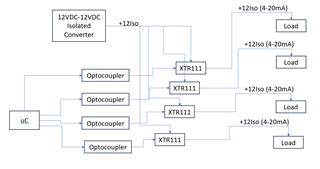
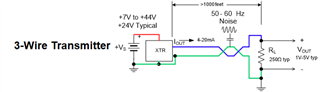
Is it possible to generate four Analog output current channels (4-20mA) using single XTR111. I am planning to use a DC-DC Isolated converter and SPI isolatar to generate multiple Analog outputs. But We also need to provide DC loop power >10V along with 4-20mA.
question is , Can we use XTR111 for this purpose. Do we have some reference design for the same with loop power
A current source adjusts the voltage to keep the current constant. When you have four loads that are even slightly different, then you need four individually regulated outputs.
I do not understand how you would get power from four loops. Please show an architecture diagram.
Hi,
I was thinking If I can use a single DC-DC Isolator and power all the 4-XTR111 IC, not sure will it work. I need a loop voltage of 12V along with 4-20mA output for all the four channels.
Input to the XTR is isolated from other grounds using optocoupler.
Input voltage is generated using PWM signals.
Attached is the block diagram.
In this diagram, all XTRs and all four loads share the same power supply and GND, and are powered from the DC-DC. If this is what you want, then it will work.
A four-channel isolator like the ISO7740 would be simpler and faster than four optocouplers.
Hi,
Pl confirm my following assumptions are correct:
1. These four current outputs can be connected to different loads.
2. XTR111 can be connected so that voltage is also given to the sensors along with 4-20mA output signal.
3. We need to provide 12Vdc and 4-20mA as Analog output using XTR111.
I will draw the schematic and confirm again.
1. Correct.
2. The XTR111 will adjust the voltage so that the desired current flows. If the load uses that current for its own supply, then this will work.
HI Suresh,
1) Can you please confirm if the load resistors share the same GND potential as the GND potential of the XTR111?
The XTR111 is a 3-wire transmitter, and in general the load resistor GND is in most cases connected to the same GND potential of the 3-wire transmitter on most standard applications.
If the load is referred to a different GND potential than the current transmitter GND, Then you need to ensure:
The external PFET transistor must be rated for the maximum potential VOUT, in other words, the external PFET transistor drain to source voltage should not exceed the rated operating range of the external PFET transistor.
Also, the XTR111 has a minimum compliance voltage, where the device requires at least 2V supply compliance/headroom at the IS pin. This means that after accounting for all the I*R voltage drops across the 4-20mA current path, including the voltage across the load at max current, and any series resistances across the current path, the IS pin needs to be allowed 2V below the XTR111 VSP supply while supplying the full-scale (20mA) Current.
2) I want to ensure I understand the application. Does this application requires to apply isolation between the microcontroller GND and XTR111 ground/loop GND? (I am assuming the XTRs are referred to the same load GND).
If the isolation is not required between the microcontroller and XTRs, in a standard 3-wire XTR111 application, the load resistor, microcontroller and XTR111 can be all connected/referred in most cases to the same GND. BUT perhaps, of course your specific application needs isolation between the microcontroller GND and current transmitter / loop supply ground.
As Clemens has mentioned, assuming all XTRs and all four loads share the same power supply and GND, and are powered from the same DC-DC supply, this will work.
Thank you and Regards,
Luis