This thread has been locked.

If you have a related question, please click the "Ask a related question" button in the top right corner. The newly created question will be automatically linked to this question.

About bias current for OPA2187

Part Number: OPA2187


Tool/software:

The output of some amplifiers changes by about 1.4 mV at temperatures between 20 and 30 degrees Celsius.

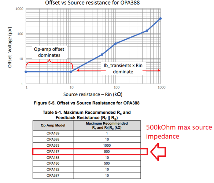
During testing, the operation changed when the resistance of the op-amp was changed to 200 kΩ, 820 kΩ, and 51 kΩ, so I think that the change in input bias current may be the trigger.

I also think that the input bias current may be changing due to temperature changes, so I would like to hear your opinion on this.

  • HI,

    The OPA2187 is a high-precision zero-drift (chopper) amplifier. Chopper amplifiers use an internal calibration circuit that uses MOSFET switches to commutate the inputs, and this calibration technique generates small current input transients within the amplifiers input bias current.

    Although some chopper amplifiers are sensitive to high source resistances, the OPA2187 has relatively low sensitivity to high source resistance, and can tolerate relatively high source resistance up to 500kΩ without issues. These transients of current on the input bias current are very small on the case of the OPA2187, and the OPA2187 is expected to provide very low offset and low offset drift with source resistances up to 500kΩ.  Please see refer to the application note below.

    Optimizing Chopper Amplifier Accuracy

     Please refer to Figure 5-5 and Table 5-1 on page 18 of the application note.  On the bench measurements, on the case of the OPAx187, at source resistances of < 500kΩ and below, the op-amp is expected to provide relatively low offset and low drift, where the offset will be expected to be much lower than <1.4mV; at around 10µV offset.

    Can you please provide the details of your bench setup to perform the offset measurement?

    Please provide the following information:

    - Kindly provide a complete schematic, including the source resistors at both inputs and feedback components, supply bypass capacitors, and any RC or circuit load at the amplifier output

    - What are the voltage supplies and input connections while performing the offset measurement

    - Is the op-amp in a gain configuration? Where in the circuit are you performing the offset measurement?

    - What specific instrument or precision voltage meter is used to measure the offset? 

    - Are there any long probes or cables connected to the OPAx187 output or inverting op-amp input that could cause instability on the setup.

    Thank you and Best Regards,

    Luis