Because of the holidays, TI E2E™ design support forum responses will be delayed from Dec. 25 through Jan. 2. Thank you for your patience.

This thread has been locked.

If you have a related question, please click the "Ask a related question" button in the top right corner. The newly created question will be automatically linked to this question.

JFE2140: JFE2140 as MC phono preamplifier

Part Number: JFE2140
Other Parts Discussed in Thread: JFE150

Tool/software:

Hi, good morning, as per another question I've posted in this support forum, I'm currently designing a tube hifi preamplifier.

A JFE2140 will be deployed as first MC-moving coil phono preamplifier; in this application, low noise is very important. Max input signal about 0.5mV - 0.8mV

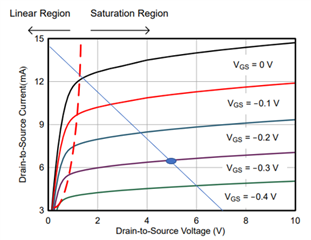
I'd like to ask you if you think my chosen operating point could be ok:

V supply: 7Volt (I don't have the possibility to rely on higher voltage within the preamp).

VDS: 5V

IDS: 6.5mA
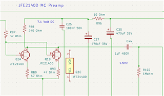
I plan to parallel the two units within the same chip, like this:
Thank you very much in advance, a good day

  • Hi Matteo,

    Yes your bias and load line plot seems reasonable, the bias current lines up with the source impedance in the data sheet.  One interesting tradeoff with biasing the JFET higher is that the 1/f noise actually starts to increase above ~2-3 mA, so this is about the right point. 

    One thing I would add, though - two JFE2140 is basically the same as a singe JFE150 - you could get the same results from a smaller package by using the JFE150, did you look into that device?

    Regards,
    Mike

  • Thanks so much Michael. Indeed, I gave a look at the JFE150 as well, but I went to JFE2140 for two reasons basically. I take the opportunity to ask you if they make sense:

    - It appears that JFE150 has a little bit higher input capacitance (24pF vs. 13pF for the 2140)

    - Furthermore - the most important reason - I plan to parallel the two sections of JFE2140, in order to get a decrease of noise of 3dB

    Thank you very much again

    Matteo

  • Hi Matteo,

    Yes - what you are saying is true, the 2140 does have lower input capacitance, but when you put two in parallel and connect the gates, then the input capacitance adds together, and you actually get 2x13 pF = 26 pF.  So, it works out to being slightly worse than the JFE150.

    It is true in JFETs that the more effective JFET area you have, the higher the gain (gm) of the JFET (which results in lower noise), but also the higher input capacitance you will have.  Adding more JFETs in parallel works for increasing the gm, but also increasing the input capacitance; in other words, as you add JFET area, you increase the total input capacitance.  Input capacitance will attenuate the signal so while the gain works in the noise benefit, the input cap. works against it.

    In order to select the JFET input size that results in the optimal gain, you'll have to know the source impedance of the input signal.  If you were to tell me it was a 13 pF piezo transducer, I would say a single JFE2140 is the correct JFET size - any more JFET and you will attenuate your input signal, any less and you will give away some noise performance by using a JFET that is not the optimal gain (or, gm).  But that is for a capacitive-type input sensor, which we see commonly in microphones.  A "voltage source" type of input won't have quite the same limitations - there the input capacitance will limit the bandwidth according to the output impedance of the voltage source.

    I believe the MC coil-type of inputs have effectively a small transformer internally - I tried to search but can't find any info. on the output impedance.  Do you happen to have any output impedance info. for your coil?

    Regards,
    Mike

  • Dear Michael, thanks for your reply. The main impedance component, for a typical MC cartridge, is the resistance. They typically exibit 10 to 30 Ohm, hence they should be loaded with 10x - at least - input impedance of the MC preamplifier. This input preamplifier resistance is set with a resistor between the signal and ground. In my project, the user will have the chance to select several different resistor figures (from 50Ohm to 500Ohm, more or less). This resistor will sit before the JFET preamplifier. Furthermore, a typical MC cart has 1-20 uH inductance (roughtly). On MC carts, input capacitance is not that important at the end, input preamplifier capacitance of 1000pF is ok. (capacitance is more important on MM cartridges, but this JFET stage serves MC ones) 

  • Hi Matteo,

    Ok - in that case it seems the application can be fine with higher input capacitance.  Give us a few days to get a more detailed response back to you, we are short a few people at the moment.

    Regards,
    Mike

  • Thanks for your support !