This thread has been locked.

If you have a related question, please click the "Ask a related question" button in the top right corner. The newly created question will be automatically linked to this question.

LM6211: What's wrong with my IEPE output circuit?

Part Number: LM6211
Other Parts Discussed in Thread: OPA992, OPA2992

Tool/software:

Hi,

I have designed a charge amplifier that requires IEPE type output.This IEPE circuit requires a constant current source for power supply.

When the current value is 8mA, it works normally. The DC output voltage should be 2.5 * 4.433=11.08V.

But in reality, sometimes the output is about 1.9V when powered by a 4mA current source. When powered by an 8mA current source, everything is normal.

Once the output is 11V, it will remain stable and work normally. Once the output is 1.9V, it remains abnormal.
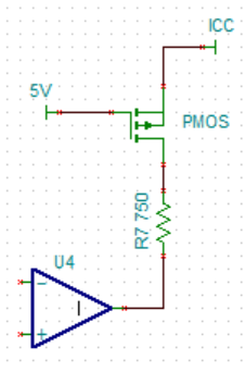
The schematic diagram is shown belowP1 is connected to IEPE input, and P2 is connected to charge output:

  • Hello Li, 

    The output ICC voltage of 1.9V is well below the operating voltage of the op amp. Because the output will likely be non linear, (stuck high or low), supply current may be higher than when op amp is running in a linear mode. If output, when under powered goes low, R7 will steal too much of the 4mA current, so voltage can't go higher.

    When under voltage, disable R7 current. There is more than one way to do that.

  • Thank you for your reply.

    Based on your suggestion, I will add an analog switch between R7 and U4. Is it feasible?
    Additionally, t
    his circuit is used for IEPE type sensors.It is powered by a 4mA current source with voltage output.Therefore, its power supply and final output are the same.The special requirement is a bandwidth of 50KHz.  Is there a better solution for IEPE sensors?

  • Li,

    This could work if there is enough ICC at min output voltage to keep PMOS on. 

    Gate could be 2.5V instead for a lower Vout min. This would probably be better. 

    During ICC below 2.5V, both 2.5V and 5V will be close to ICC so PMOS off either way.

    OPA992 or dual OPA2992 may be another option. 

    Lastly R5 doesn't need to match R8, there is little common mode current to cancel, R5 is mostly a noise source.  

  • Thank you. I want to give it a try.