Because of the Thanksgiving holiday in the U.S., TI E2E™ design support forum responses may be delayed from November 25 through December 2. Thank you for your patience.

TLV9064: Design 120Khz, 3mA peak SINE waveform which can be adjustable

Part Number: TLV9064
Other Parts Discussed in Thread: TLV906X

Tool/software:

Hi team,

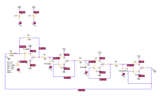
This is from the optical module suppliers requirement. They need to design 120Khz, 3mA peak SINE waveform which can be adjustable. I think that there will be 2 parts. The first part is used to generate SINE waveform while the second part is used to convert voltage to current. So as below picture, do we have any formula to calculate the amplitude and frequency. The customers need to adjust them. Is there any possibility to only adjust amplitude, such as adding some signal? If convenient, could you please also help give a simulation as reference?
  • Hi Hale,

    I can start building up a schematic for each stage. What level of accuracy is required here? 

    There is a non insignificant chance that this circuit will require tuning with adjustable potentiometers and likely adjustable capacitors to dial in the desired frequency of oscillation. 

    The accurate amplitude control in the Howland current pump will be a real challenge as well.

    The accuracy requirements for this application will help me understand if this is possible with TLV906x.

    Best,

    Jacob

  • Hi Jacob,

    thanks for your explanation.

    1. I think that 0.1mA ~ 0.2mA step is enough. Can TLV906x support? which spec can influence accuracy?

    2. And please help share how to design the frequency and amplitude.

    3. And if you don't think this solution is acceptable, do you have any other solution to meet the customers' requirement. We ever think that use op-amp+RC to convert PWM to SINE. But also not sure whether this is good solution. Because we use potentiometer to adjust the amplitude while we don't have potentiometer roadmap. So if can use some solution to realize, we can have a breakthrough in such application.

  • Hi Hale, 

    This requirement for .1-.2 mA is not too bad. What is the frequency accuracy requirement in % for the application?

    I will design a 3-4 stage oscillator and one more amp for the Howland current pump. 

    PWM to sine could work. Honestly this can be a much better approach for sourcing the frequency generation. 

    Has the customer seen our Digi-pot portfolio? https://www.ti.com/data-converters/digital-potentiometer/products.html#

    Does the customer use a microcontroller in their design?

    Thanks,

    Jacob

  • Hi Jacob,

    I think that frequency accuracy is not important for customers. If make sure the frequency, they will not change the circuit, while the amplitude need to be adjusted. 

    This application has an MCU while they are evaluating our digi-pot.

    Could you help provide some simulation and formula?

  • Hi Hale,

    Here is the design for the oscillator:

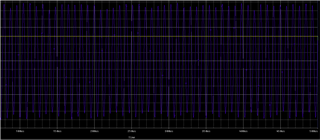
    Here is the output:

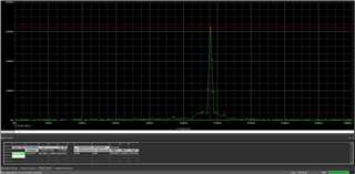
    Here is the FFT from my circuit: ~115kHz

    I still need to work on the Howland current pump portion of the design, but this would go after the oscillator.

    Thanks,

    Jacob

  • Hi Jacob,

    thanks. Could you help share the simulation with us?

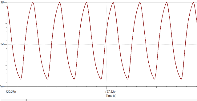
    I try to use TINA simulation with same parameter, but the simulation is as below. There is a little distortion. Could you help give some comments about how to improve. And I am still a little confused about how to calculate the frequency and amplitude

  • Hi Hale,

    Yes, there will sometimes be distortion in the waveforms from an oscillator like this. 

    Here is the PFTI design: tlv9064sine_generator_120khz-2024-11-05T17-47.zip

    Amplitude will be determined by the inherent speed of the OPA. This is one reason why I am inclined to see the PWM with a Digipot here instead of this method. 

    Frequency calc comes from this app note:

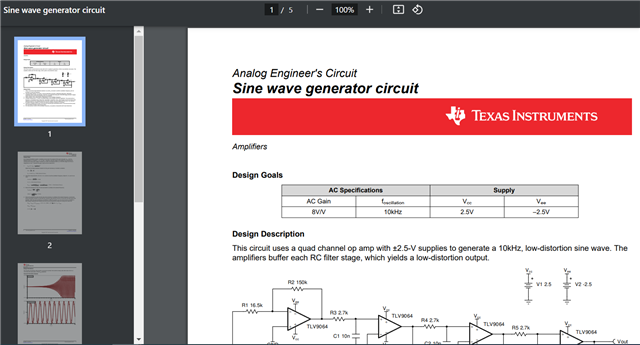
    Sine wave generator circuit

    Please let me know if you have any questions,

    Best,

    Jacob