This thread has been locked.

If you have a related question, please click the "Ask a related question" button in the top right corner. The newly created question will be automatically linked to this question.

TLV274: Wave form distorted during simulation

Part Number: TLV274
Other Parts Discussed in Thread: TLV271

Tool/software:

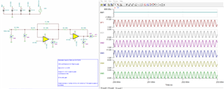
I was simulating a circuit that uses a TLV274IPW. I used the TLV271 pspice file in a Tina TI simulator. I am getting a distortion on the voltage output waveform. I am not sure if it is the model that I am using or if I am violating something in the chip. The current waveform is flatting out at the my peaks though I don't believe I am exceeding the current output of the device. 

If I attach the sim file and it output (which I have to figure out, can someone help me define what I am doing wrong?

T4 Simulation.TSC

  • Hi Glenn, 

    Could you clarify what this circuit is used for? Also I noticed the output of the first stage op amp is being fed into the second stage but also into PM2. What is purpose of this? 

    Regards,
    Ashley

  • It is used for driving a resolver. PM2 is a power meter used in measuring the output power. I used it to see if I was over driving the op amp. I don't really need it for circuit function. It is the first time I've actually used it.

  • Hi Glenn,

    When I remove the second stage output PM2 and inductor, the transient waveform no longer has the distortion. 

    What is the load that will be directly after the second stage op amp? We can simulate it for accuracy of how the op amp will interact with the load condition. 

    Thank you!
    Regards,
    Ashley

  • Yes, removing PM2 has no effect. Removing the inductor is removing the load. I am testing the circuit against the load. This is the actual inductive value that the circuit drives. I don't see this in my prototype but I do see it in this simulation.

    I was thinking maybe there was some variance between the TLV274IPW chip in my prototype and the TL271 simulation device I use in Tina TI. I was told that is how I could simulate the circuit.

    I am using the simulator to test out the tolerances in the resolvers inductive input.

  • Hi Glenn, 

    Do you have a series resistor connected to the inductive load? In taking out the power meter, you are still left with an inductor directly connected to the op amp output which can cause issues in your simulation. 

    Regards,
    Ashley