This thread has been locked.

If you have a related question, please click the "Ask a related question" button in the top right corner. The newly created question will be automatically linked to this question.

LM2904B-Q1: output abnormal

Part Number: LM2904B-Q1

Tool/software:

Hi team, 

Need your help to check below problem. 

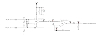
V_CP1 is about 23V. This is for high side current sensing application. CS3_SP4 and CS3_SN4 are connected to a shunt resistor. When there is no current flow into the shunt. The output on T310 is about 700mV. This is extremely exceed the offset voltage of LM2904B-Q1. Could you please check this?  

Thanks!

Ethan Wen

  • Hey Ethan,

    There are two issues here. The issue you are seeing is because the output stage of the LM2904B-Q1 is not rail to rail. When there is no current, and therefore no input voltage differential, the output of a difference amplifier should be 0. However, the LM2904B-Q1 will output as close to 0 as it can, which in this case is 700mV. This is explained in section 3.1 of the following app note: https://www.ti.com/lit/an/sloa277b/sloa277b.pdf

    Additionally, the input filtering on the first channel of the amplifier will cause unstable operation. More explanation on this can be found in the following article: https://www.planetanalog.com/a-closer-look-at-discrete-difference-amplifier-implementation/

    Best,
    Jerry

  • Hi Jerry, 

    I will go through the article later. 

    Customer mentioned that the same design used in low side current sensing doesn't have such high output error. I don't understand why high side or low side current sensing cause this difference. 

    For the input filter circuit, what is your suggestion to make it stable? 

    Thanks!

    Ethan Wen

  • Hello Ethan,

    The reason this circuit works for low side but not for high side is because of the output current necessary to drive the output to 0V. I'm assuming the common-mode of the LM2904B-Q1 is in the valid range, and is not the same as V_CP1, otherwise this is a third separate issue.

    But assuming that the common-mode voltage is 20V, the amplifier will have to output enough current to drive the node at T300 to 0V. This will be 20V/20k, or 1mA.

    When the op amp is outputting 1mA, the VOL is 750mV.

    The suggestion is contained within the article I linked in figure 2 and figure 17.

    Best,
    Jerry