This thread has been locked.

If you have a related question, please click the "Ask a related question" button in the top right corner. The newly created question will be automatically linked to this question.

OPA838: Calculation of the transimpedance amplifier

Part Number: OPA838

Tool/software:

I have basic questions about the following configuration of an Op-Amp, which is transimpedance amplifier, I would appreciate your help to help me understand this:
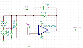
First question, considering that the positive input of the Op-Amp is connected to GND, then Op-Amp will try to keep the negative input voltage also to zero(GND), then there is no voltage different in the inputs of the Ap-Amp, so I assume the output voltage should be zero finally, considering the gain will be multiplied by zero but why it is not zero?

I will do my best to answer based on my current knowledge and make an active effort. Please feel free to correct me if I am mistaken.

Considering there is current flow through R1, then there is a voltage across this resistor, so the output voltage will adjust itself in a way that the negative input pin is still zero, so how much this argument is correct? but still how can I justify the previous argument that I made? when there is no potential difference between positive and negative, then the output should be zero?! to be this too contradicts, unless I am missing a critical point here.

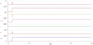
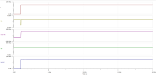
I also have plotted the behavior of these signals:
Thanks in advance for your help.

Regards 

  • I could also plot the voltage difference between V+ and V-  (Vpn) as follows:

    Even if Vp is directly connected to GND, it is not zero, it is around 2.2uV.

  • Hi Behnam, 

    You have the right idea with your thinking but one thing to keep in mind is that the inputs of an amplifier are never actually equal. Ultimately the output of the amplifier is determined by Vout = Aol * (IN+ - IN-). Ultimately the amplifier MUST have a small differential input voltage in order to get an output voltage. We often just approximate that to zero because the value of Aol is very large. However, if the inputs were actually both perfectly equal to zero then the output would also be zero as you were thinking. 

    When we attached feedback to the amplifier, it means that the IN- pin will proportionally follow the output voltage. So the amplifiers output voltage will adjust until it satisfies the above Aol equation. If we assume Aol is very large then we can basically say that the output of the amplifier will adjust until the inputs are approximately equal to each other. 

    In the case of the transimpedance amplifier the photodiode causes a current to flow through Rf. In this case the output voltage will adjust based on i*Rf in order to keep the nearly equal. 

    In the model you will see a small input differential voltage based on the finite Aol value. The small voltage you are seeing directly on the IN+ pin is just due to some series impedance that is in the model creating a voltage because of the bias current from the pin. 

    Best, 

    Jacob