Because of the Thanksgiving holiday in the U.S., TI E2E™ design support forum responses may be delayed from November 25 through December 2. Thank you for your patience.

TLV1852: RE: Amplification of Amperage to suit My Needs of a Datasheet...

Part Number: TLV1852
Other Parts Discussed in Thread: THS4567, TXU0101, LM358-N, LM358, LM258, AM67A

Tool/software:

Hey There,

Seth here. Okay and so, I have a SBC that outputs 3.3v signals from beagleboard.org. I can use the CMOS signals to push, and right now I am not sure if this is going to be the SBC used, specific amounts of mA per pin.

I am currently worried, though. The datasheet of the DM332T from StepperOnline.com is dictating a min-max with a "typical" mA at 10mA while the minimum is 7mA.

The current board used does not push out an output of 7mA. It handles less mA per pin, i.e. thus getting in my way currently. I was thinking of using a comparator or other op-amp type to amplify the amperage of the pin but I am without this knowledge. 

For now, I see op-amp types used with resistors to create specific circuitry. 

I have a lot to learn and need some support on purchasing, types of amplifiers, and exactly how to get at least 7mA out of 4mA...

.......................................

Here is a list of Ideas.

......................................

1. I need to be able to amplify the amperage to a dedicated range (7mA to 10mA).

2. I need a DIP package for testing.

3. and... I will need at least a whitepaper or some type of evidence that what you are proposing will work. 

Is this asking a lot knowing that I can get turned away? Yes. I am way over budget already and still trying to make things work. 

Seth

P.S. If you have any words of wisdom, please add them to the below sections for text.

  • Seth,

    All I know is this "Logic Signal Current: 7~16mA(Typical 10mA)", I didn't find the data sheet easily. Do me a favor and describe what is the valid low and high signal looks like. Is input low and high a voltage or a current? 

  • THS4567

    I have been doing a bit of research and I have come to the realization that there is no perfection. I found a THS4567. It has output at 2mA. I am not sure if this is an additional 2mA or 2mA total. Off to read the datasheet now.

    Seth

    P.S. Oh...I see you just replied. Let me reply to your questions. I will rehash this post later.

  • https://www.omc-stepperonline.com/download/DM332T.pdf

    That is the datasheet for the stepper driver. Current. High is current. 

    Seth

    P.S. I cannot. The level is higher than what I can provide currently. 

  • Seth,

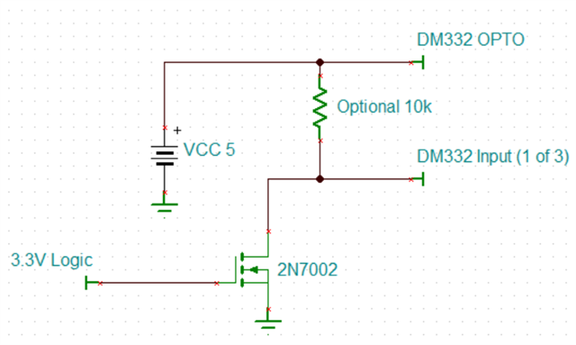
    This is an easy way to convert 3.3V logic to sinking opto-coupler drive. 

  • Seth,

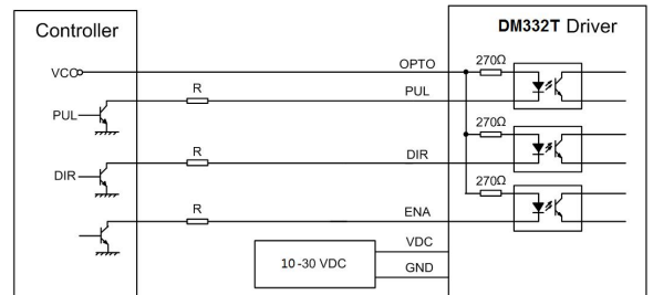
    If you do not have 5V, you can use your motor drive supply (10V to 30V).

    Add a resistor R , if OPTO is higher than 5V

  • I understand. I was going for non-noticeable or less hassle. I get what you are telling me since I saw the same "schematic."

    Sorry, I just got what you meant earlier. "Valid high and low signal look like," threw me for a loop. You wanted an oscilloscope reading for output?

    Seth

    P.S. The first and second understandings are perfect really. I have sys_5v (I think) and vdd_5v only which should not be connected to the board (I think) and dongle/module/driver. Outside of that idea, I figured I could amplify the mA by four mA and go from that point forward. I must be missing something. 

    I can try the op-amp idea if necessary. I have some in stock. I just did not want to use the op-amp for this purpose. This was the reason I was reaching out. Thank you, sir. I appreciate your time and effort in helping me in this endeavor. I will call it closed now. I actually may not have the correct op-amps. So, I may be searching again?

  • Is it a fact that even though my mA rating per pin is about 4mA, using a 5v supply should grant me access to the driver in question?

    Seth

  • Hey Sir,

    Mr. Ron, have you used the TXU0101. I see I can get 12mA at 5v but I am not sure this incorporates reverse polarity protection (still reading). Also, I see boost converters are lowering current for the sake of making voltage higher. Is there an opposing CMOS type anti-boost amplifier (so to say)?

    Seth

  • Seth,

    I see no reason to over complicate this otherwise simple interface. 

    I have a SBC that outputs 3.3v signals from beagleboard.org.

    I assume this is GPIO digital signals. They would be 3.3V for high and 0V for low. This is fine to drive gate of 2N7002. 

    The stepper driver is a simple opto coupler LED and a built in resistor. The LED just needs to turn on and off. 

  • Hey Ron,

    Sorry. All I have in stock is the 

    LM358-N

    I have just enough to build this machine. Do you think that this "drop-in" will replace a 2N7002 with ease or should this not be used?
    Seth
  • Seth,

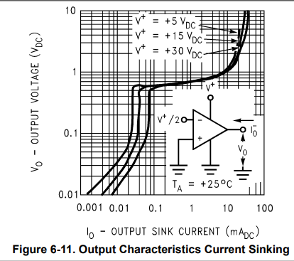
    Typical LM358-N can sink 10mA while losing about 1V. That should be good enough for now. It will be slower which is fine if the pulses are not too fast. 

  • Thank you again...funny thing here. I tried a set up of circuitry and received a hot motor. Ouch is what I have to say...

    Anyway, all fun aside, I am mistaken on Inverting and Non-Inverting signals so far on the LM358N. Do I attach a GPIO to the negative and GND the positive regarding the Non and Inverting pins on the chip?

    Seth

    P.S. Or...would I need a type of filter to bypass the errors in overheating the motor?

  • 8.8 on page 16 of the datasheet shows a Driving TTL signal schematic...

    1. It shows a DM54xx.

    2. Would this be a go-to for driving the "OPTO" pin on the DM332T driver?

    Seth

    P.S. I mean...I presumably thought this was an op-amp with ease of use. I have been delighted to find that it really is easy to use. 

    Outside of it being an ease to use, I have not found the DM54xx "diode" or part from TI.com. Would any two-input/one output transistor work? I will try a specific AND Gate and see how far I get...

  • Seth,

    Connect GPIO output to one input and connect 1.65V (exact value not critical at all) to the other input. You can make this voltage with a voltage divider powered by either 5V or 3.3V. Connect output to DM332T. 

    I have not found the DM54xx "diode" or part from TI.com

    I'm confused. why do you need a diode?

  • I thought the DM54xx was a diode at first. Okay, GPIO at 3.3v to one input and the other input gets ~1.65v. I will make the voltage divider.

    5v or 3.3v should do the trick after connecting the voltage divider circuit. Now, is the output of the circuit connected to enable or the other two pins or OPTO?

    Seth

  • Hey Sir, we are in luck. I have two 1kohm resistors! I will report back briefly with the circuit output on OPTO.

    Seth

  • Seth,

    You need up to 3 channels of LM358-N to talk to the motor driver. 

  • I understand but I have only two outputs from that op-amp (LM358N). I actually have two op-amps, i.e. both are LM358N types.

    Seth

  • Hey...Sir,

    I think I got the three GPIO pins mapped out and the divider circuits made with the 3.3v (GPIO) to 1.65v (v div) to GND and the other inverting/non-inverting pins. 

    That sounds complicated...but:

    1. Some of the divider circuits are connected GND, of course, and then to inverting pins on the LM358N chips.

    2. While other divider circuits are not so...

    3. The voltage divider circuits are to GND, of course, and then to non-inverting pins on the LM358N chips. 

    I just got lazy.

    Seth

    P.S. I should have been uniformly stout with the circuitry, i.e. hence the laziness clause. Anyway, I will be testing after lunch. Thank you thus far, sir. I will reply once the testing is finalized.

  • Hey Ron,

    Seth here once more or again...

    I think I figured out my issue. When I have a 3.3v to 1.65v transition within the LM358N to go to one output (my driver (DM332T)), I get flawless GPIO access but...

    There is something that formally confused me. OPTO needs 5v while GPIO is 3.3v. I have some dedicated vdd_5v and sys_5v pins but no way to GND them from the board without other formal circuitry (I think). 

    I am not using the enable pin. It is enabled by default. So, I will not need a GPIO pin for the enable pin. Does that sound right? No, I do not think it sounds correct. I should use the enable to stop supply if things get awkward. This would be my third and final GPIO. 

    If my board supplies sys_5v but I am worried about EMI or backflow, do you think that the voltage divider on the 5v pin is a correct circuit? 

    Seth

    P.S. If all else fails, I will just use a separate PSU or wall adapter for the query of 5v supplies. But is there something keeping me from grounding 5v on 3.3v GNDs? 

  • Seth,

    As long as supplies are isolated or have a common ground then connecting grounds together is fine. If you don't need Enable then just one LM258 is needed. LM358 doesn't care (no damage) if input voltage is greater the LM258 supply voltage.

  • Thank you for sticking with me on the project so far. I just think my logic is off now.

    I type the source, it compiles, runs fine but only the motor is excited for whatever reason, e.g. probably the enable line is an On no matter if I use it or not.

    I will test the circuitry again...

    From your build using my LM358N op-amps, I was thinking that the circuit I have made is incorrect. It is either the logic or the circuitry. I know my GPIO pins are okay and working. 

    So, I have LTspice for circuitry making on my hard drive. The software LTspice does not carry a LM358N in stock. So, making the build from/to board/LM358N/driver is a no-go for now. I will research some other tools to use for making the circuit to show you.

    Am I still supposed to use the voltage dividers for the GPIO to LM358N chips?

    Seth

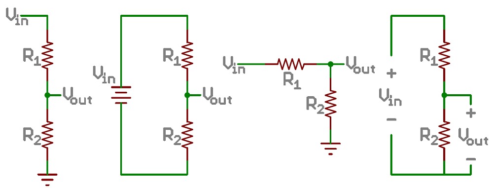
    P.S. So something like this third to the right circuit in the photo?

    I C & P that set of voltage dividers from sparkfun. 

  • Seth,

    All images are the same circuit. VIN is 5V, VOUT is roughly 1.65V. To make it easier 2.5V is fine.

  • Hey sir,

    Seth here. So, from what I understand now, the GPIO high of the (say am335x and/or AM67A), are at about 2.5v (nominal) as output when switching. I am not sure this is evidence that this will work or not. I just got an update from someone. Anyway, I think we should stop our communications. I am starting to feel like my circuits and/or unknown factors in the build are creating nothing to work thus far.

    Seth

    P.S. I thank you so far for your guidance and assistance. 

  • So, I just had some help yesterday too. When I input 5v into the Vin of the op-amp, the output is 5v. I think I was mistaken on this idea. I will keep the voltage divider also...

    Thank you again. So, from what this fellow told me, I need an external supply of 5v and this is not from the board voltage. 

    I will try to wire up some 5v supplies and hopefully soon. I will return service.

    Seth