This thread has been locked.

If you have a related question, please click the "Ask a related question" button in the top right corner. The newly created question will be automatically linked to this question.

INA281: Output glitch when Vcc brown in/brown out

Part Number: INA281

Tool/software:

Hi Team

Customer found there is a glitch when VCC brown in/brown out. and the peak is 1.1V of glitch and Vcc peak value is 1.2V.

I noticed that the Vss rang of INA281 is greater than 2.7V. So I am not sure if this is the reason which cause this unexpected performance? 

  • Hi Harry,

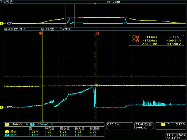
    Can you please clarify: Are you saying that as VCC crosses 2.7V the output spikes? What is the value of VCC at the red line in the image below? Also what is the peak value of VCC in this picture?

    If the VCC peak value is 1.2V like you said, then this is outside of our operating conditions and we do not specify how the device will operate under those conditions.

    Please let me know.

    Best,

    Holly

  • Holly

    What I mean is Vss's DS requirement is greater than 2.7V.

    Customer found when they applied Vss brown in/ brown out,  there is a glitch when Vcc=1.2V whatever the final Vcc value equal( in their system, the Vcc will be 12V finally).  and actually there is not current in input side. 

    Can you help to try if you can reproduce this phenomenon in EVM?

  • Harry,

    I think it would be best that we clarify the terms we are using. Vs = supply voltage (that is the spec in the DS you are referencing)

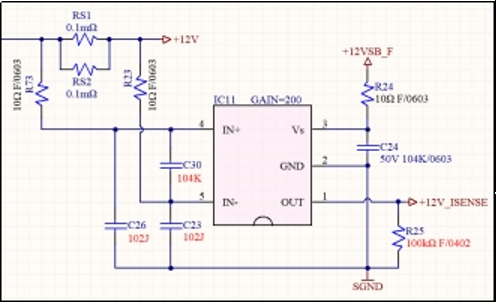
    VCC is another name for Vs, so I am wondering if you mean VCM (common mode voltage)?  However, based on your photo you say VCC is pin 3 which is the same as Vs. 

            1. Please let me know what you mean when you say Vs  and what you mean when you say VCC. 

    When Vs/VCC is below 2.7V it is outside of our recommended operating conditions.

            2. Please explain the test you are doing. Are you starting the supply voltage (Vs) at 0V and then slowly stepping up to 2.7V? If not, what voltages are you applying to Vs (pin 3) and for how long?

    Please detail what you did and I will test this on my end once I know.

    BR,

    Holly

  • Hi Holly

    Let me clarify the items. 1. Yes, what I mean of Vcc&Vs is supply power on Pin3. the following is the schematic, RS1&RS2 are current sense resistor+12V is the output voltage, 12VSB is standby power for INA. Customer used this device as server PSU output current sense, and 2 pcs PSUs works in parallel.

    what we do:

    a. We found this problem in PSU system test. After the AC input is turned off, the voltage of INA281B4IDBVR pin 1 will rise until +12VSB_F drops to 1.2V:

    b. Then we use a DC source to power the IC, slowly increase or decrease the voltage, and short-circuit the input pins 4 and 5. When VCC is around 1.2V, the voltage on pin 1 will surge.


    My questions are:

    1.Why this abnormal phenomenon happen? understand the Vs is below the recommendation rang, but can you explain more what part of internal is impacted? 

    2. Can you reproduce this phenomenon on EVM? 

  • Hi Harry,

    Thank you for this information.

    1. As you said, the Vs it outside of DS range. This means the device is powering down and as it does so, different components turn off at different times. This is why we see a voltage spike. It seems like the circuitry that is driving the output stage turns off before other things which is why Vout will temporarily track Vs until the rest of the components turn off.

    2. Reproducing this on the EVM will not provide us with any new information.

    I do have some tips on how to minimize this effect. I would recommend putting a 10kΩ pull down resistor on the Vs pin. In your scope shot we can see that Vs is pulled down fast at first, but around 1.2V it starts to very slowly fall towards GND and that is a sign of weak pull down. If you can get the supply pulled down faster you might be able to minimize this Vout voltage spike.

    - I would first try adding a pull down on Vs (pin 3) only.

    - Then try adding a pull down on Vout (pin 1) only.

    - Then try adding a pull down on both.

    Once you find a method that works you can try reducing the resistor to minimize power loss.

    I hope this helps.

    BR,

    Holly