This thread has been locked.

If you have a related question, please click the "Ask a related question" button in the top right corner. The newly created question will be automatically linked to this question.

Audio forum

Part Number: TAS6584-Q1

Tool/software:

Hi team:

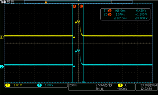
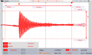
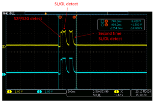
While powering on the unit,There is no input signal at this time, can hear some digital interference noise (sounds like "da-da") out of the speaker.

Is this the sound produced by the power amplifier chip during load detection?

The attachment is the recorded audio signal.

  • Hi Haiqing

      Yes, it's quite possible caused by the DC Load Diag. Could check register 0x72 and 0x73, to find if the channel state is Load Diag. 

  • Hi shadow:

    The registers 0x72 and 0x73 can only be read. If it can be read that this register has entered the LOAD DIAG state during startup. Is this' da da 'sound produced by the chip itself?

  • Hi Haiqing

    If it can be read that this register has entered the LOAD DIAG state during startup. Is this' da da 'sound produced by the chip itself?

    Yes.

    And also could check register 0xC0 and 0xC1, it possibly report open load, normally would seen with capacitor coupled speaker, has very large DC resistance.

    Could set value 0x01 into register 0xB0, to bypass DC load diag.

  • Hi shadow:

    Set value 0x01 into register 0xB0, this sound still exists. Can't DC load diagnostics be skipped during chip initialization?

  • Hi Haiqing

    Set value 0x01 into register 0xB0, this sound still exists.

    Set value 0x01 into register 0xB0, the DC LDG will stop. If there's still the sound, it's either I2C has some problem, or the sound has some other reasons.

    Can't DC load diagnostics be skipped during chip initialization?

    At startup, only pull up PD pin, still keep STBY pin low, set 0x81 into register 0xB0, could totally stop any DC LDG.

  • Hi shadow:

    What is the amplitude and frequency of the detection signal emitted by the chip? Do you have accurate data?

  • Hi Haiqing

      A typical DC load Diag waveform as below picture shows. Total time 150ms, amplitude 1.5V.

  • Hi shadow:

    This is the data we tested (disconnecting the SDIN of the amp during testing), which is different from the test data you provided. Excuse me, is this waveform correct?

  • Hi Haiqing

      It's not the normal waveform. Besides, the waveform you tested, is it the differential voltage between OUTP to OUTM, or it's the OUT to GND voltage? And your probe settings, is it AC coupling, or DC coupling? Have a try with DC coupling, and test OUT to GND, I want to make sure the device already in PLAY mode or not.

      If you could read the register value, it would be much easier for the debug. Register 0x72 and 0x73 could tell you the channel state, and 0x80 to 0x8A could tell you if there's any fault happens.

  • Hi Hi shadow:

    The above wave is measured from out to outm. The probe setup is AC coupled.
    The probe uses DC coupling and tests the wave form from out to GND as follows, which is very close to the wave form you provide.

  • Haiqing,

    This is exactly the DC load diagnositic waveform. 

    To proof this waveform is speaker da-da related, please connect all channel output with 4ohm resistor load.  the da-da is expected to disappear.

    Dylan

  • Hi Dylan:

    This waveform is tested with output load (load condition: PBTL: 4ohm, BTL: 16ohm). Test PBTL channel, probe set to AC coupling, measured from outp to GND.

  • Hi Haiqing

     Your waveform shows the device detected open load or short load.

     If you compare with my waveform, will find it has the second time SL/OL detect, same as below example. Because when device detected fault, it will quickly do it the second time, then report it.

     Perhaps your speaker manufacture says it's 4ohm/16ohm speaker, but it's usually the 1KHz load value. If your speaker has internal coupled capacitor, will have much large resistance under DC test. Could have a try with multimeter.

     Or, you mentioned PBTL, it's also possible you didn't successfully set the register, to make the device works in PBTL mode, also possible has incorrect detect results.

      Either the case, you'll need to make sure your I2C could work without problem. This device can't work without correct I2C command.

  • Hi shadow:

    The output of the power amplifier chip (PBTL+BTL) is correct now, and the system has detected an open circuit, which may be due to a group of outputs (output 4) being in a suspended state. Please ask DC load diagnostics and What is the difference between AC load diagnostics. The da da sound above is emitted when the power amplifier chip starts which type of detection.

  • Hi Haiqing

    Please ask DC load diagnostics and What is the difference between AC load diagnostics.

    AC load diag, device will produce a default 18.75KHz (could adjust) sinewave, and check what is the current with the same frequency. Together with voltage and current detected, device calculate what is the impedance on the load.

    The da da sound above is emitted when the power amplifier chip starts which type of detection.

    The AC load diag will need you to send correct I2C command to perform. And your wavefrom shows only doing the DC diag.