Tool/software:
Hi team,
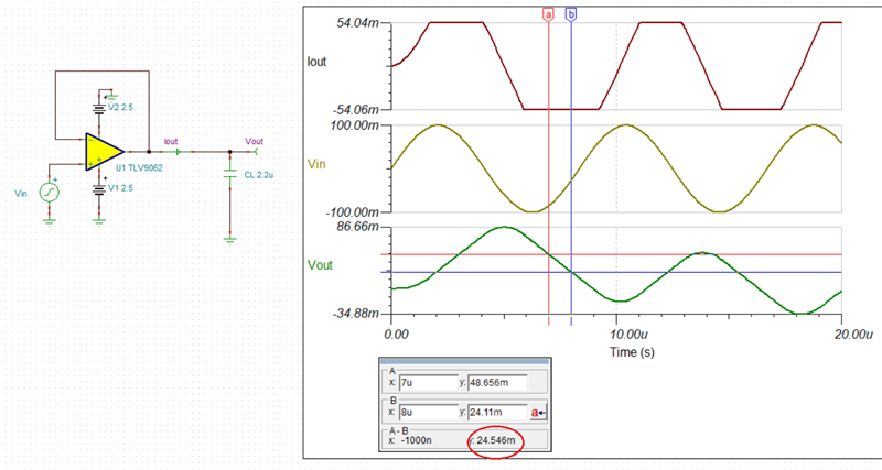
My customers use TLV9061 as voltage follower. The simulation is as below:
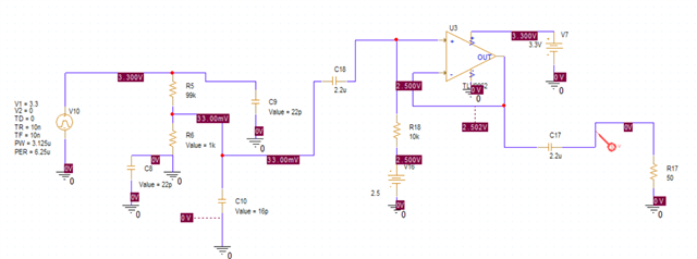
But in the actual test, they found that when they added a 50ohm load, like R17, the output which is 5~6mV, can't follow the input which is below 100mV; when they keep the load open, the output is normal which is same as input voltage. So I am not sure whether the Zo influence on the output, which is just 100ohm. Can it support to drive 50ohm load?