This thread has been locked.

If you have a related question, please click the "Ask a related question" button in the top right corner. The newly created question will be automatically linked to this question.

OPA340 summation circuit

Other Parts Discussed in Thread: OPA340, TINA-TI

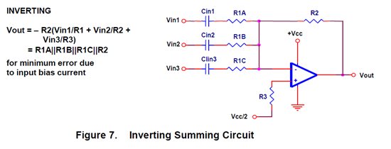
I am following the advice on Application Report SLOA058 Figure 7 to use an OPA340 as a summation circuit.

I am using a Vcc of 5V, R1A = R1B = R2 = 1kOhm (for gain of 1) so R3 = 330Ohms (There is no R1C in my circuit, only two inputs).

I have set up a difference circuit (Figure 8) with no problems, however the summation circuit is giving an unexpected output.
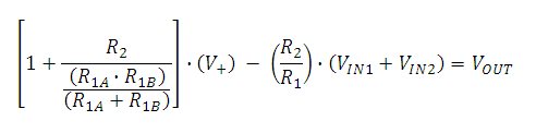

By KCL:

 (((Vin1)-(V-))/R1A)+(((Vin2)-(V-))/R1B) = (((V-)-(Vout))/R2).    [Eqn 1]

For an ideal op amp (V-) = (V+) = 0, so Eqn 1 becomes

(R2/R1)(Vin1+Vin2) = Vout                                                           [Eqn 2]

for equal R1A and R1B. This gives the desired summing effect with gain (R2/R1).


However, by testing I have found that (V-) does not equal (V+) (a difference of half a volt) and neither equate to zero. So while the first equation is still found to be valid it does not become the second equation and the summation effect does not occur.


Any suggestions as to why V- does not become 0?

  • RH;

    Rather than equations, can you post the circuit in TINA-TI showing the input voltages and output voltages?

  • Hi R H,

    Welcome to the TI E2E forums!

    Here is a picture of what I think your circuit should look like:

    You didn't mention putting a voltage supply on V+. It sounds like you grounded it. Your circuit will not work without applying a voltage to V+.

    Your equation should be -(R2/R1)(Vin1+Vin2) = Vout, don't forget the negative sign! You are summing inputs into the inverting input of the op amp.

    With only a single power supply of 5V, your op amp cannot output a negative voltage, to correct this you must apply a bias to the non-inverting input (the 2.5V seen in the image above), or use bipolar supplies.


    Regards,
    Chris

  • Where is the 330 ohm resistor?

  • Hi Neil,

    The app note places it in series with the non-inverting input (R3).

    It may act as a protection to limit input current into the op amp if the non-inverting imput voltage goes above +Vcc. I left it out because I don't see that being an issue and removing it removes a small noise source.

    Regards,
    Chris

  • Hello again. Thanks for the welcome and the quick reply.

    Christopher, in your first reply your diagram has voltage sources at the op amp inputs. Are you telling me that is what I am missing? Or maybe I have not been clear. When I wrote V- and V+, I meant the voltage at the inverting and non-inverting inputs respectively, I did not mean to say I had applied a voltage there. The only voltages I am applying is Vin1 and Vin2. So it is basically a standard summation circuit as laid out in Figure 7.

    Also, when you say I need to apply a bias to the non-inverting input for a virtual ground, I have done this with a voltage reference (built from another OPA340) and this outputs 2.5V at the Vcc/2 point in Figure 7.

    My circuit is just like that in Figure 7 (except for only two inputs; Vin1 and Vin2). The reason I mentioned voltage values at the inverting (V-) and non-inverting (V+) nodes is because the output was not returning the sum, so I measured the voltages at all the nodes and found that at the two inputs of the op amps the voltages were not as the theory I am familiar with would suggest.

    I asked why the two inputs were not at zero because I thought that was my problem, I assumed Figure 7 was correct. Are you saying I need to apply voltages at the inputs as well? If so why, and what magnitude of voltage?

    Many thanks,

    Rob.

  • Hi Rob,

    Your thinking is correct. When the op amp is working correctly the V+ and V- voltages (voltages at the inverting and non-inverting op amp inputs) should be equal. This is because your using negative feedback and the op amp behavior will be to output whatever voltage (within reason) to make the inputs equal.

    The limitation to this is that the op amp output cannot go above Vcc or below ground when using a single supply of Vcc, and usually there is an output voltage swing limitation that limits the op output even more (but the op amp will usually be able to output voltage close to the positive and negative supply rails). In this condition the output is "saturated".

    Now, with that limitation in mind here is what I think is happening. In the equation "-(R2/R1)(Vin1+Vin2) = Vout", you are assuming that V+ is grounded. If V+ is not grounded then the equation becomes:

    Which, for your resistors values of R1A = R1B = R2 = R1 = 1k reduces to:

    Finally, with V+ = 2.5V then the equation is "7.5 - (Vin1+Vin2) = Vout". The summation of Vin1 and Vin2 is subtracted from 7.5V. When Vout is not in the range of 0 to 5V then the op amp output saturates at either rail and the condition V+ = V- is no longer valid. Therefore, Vin1+Vin2 is limited to values of 2.5V to 7.5V.

    Regards,
    Chris

  • Rob,

    I should of asked you before, are you using the DC coupling capacitors from figure 7 in the Application Report SLOA058?

    I left those out of my analysis, but those will also affect the transfer function. If you do use them then I believe your transfer function simplifies to Vin+ - (Vin1+Vin2) = Vout BUT, they will block DC voltages from VIN1 and VIN2 so that you can only add AC signals.

    Regards,
    Chris

  • Hi Chris,

    Sorry for not getting back sooner.

    Yes that is exactly what is happening, thank you very much.

    I have only been using DC to test the circuit, although I plan to test with AC as this is what the circuit will be used for. I will therefore add the AC coupling capacitors as per Figure 7. You say this will change the output equation to 2.5 - (Vin1+Vin2). Could you say how you got to this equation?

    Thanks again for solving my problem,

    Rob.

  • Hi Rob,

    You are applying voltages to both the inverting and non-inverting terminals of the op amp. In essence you have both an inverting op amp configuration AND a non-inverting op amp configuration together. (Recall, that the gain of an inverting op amp is not the same as a non-inverting op amp).

    When you DO NOT include the AC coupling capacitors, the V+ voltage input to the non-inverting input of the op amp sees a non-inverting amplifier with a gain larger than 1 (=3).
    When you DO include the AC coupling capacitors, you change the feedback impedance ratio so that the gain of the NON-INVERTING amplifier is 1.

    The equation "Vout = 2.5 - (Vin1 + Vin2)" is a simplification of the more general equation for your circuit:

    Vout = [V+ x (non-inverting gain)]  -  [(Vin1 + Vin2) x (inverting gain)]

    ...this is found using superposition.

    Regards,
    Chris