This thread has been locked.

If you have a related question, please click the "Ask a related question" button in the top right corner. The newly created question will be automatically linked to this question.

LM2907-N: Clarification

Part Number: LM2907-N

Tool/software:

Hello Team,

Posting on behalf of my customer:

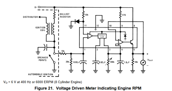
I need to know if the capacitors shown on this drawing are all electrolytic capacitors or other. The cct. diagram that I'm referring to is contained in your IC information sheet(s) for your IC # LM2907N/NOPB specifically the "voltage driven meter indicating engine RPM" (figure 21 on page 17)
Regards,
Renan

  • Hi Renan,

    This was an old National Semiconductor device. I'm pretty sure their drawing convention back then always marked their capacitors what some people consider to be electrolytic with one of the lines curved rather than two parallel lines. I'm also basing this on the fact that those capacitance values are well within the common ceramic capacitance range but below what you see electrolytic values at. 

    In short, I'm confident these are ceramic capacitors. 

    Hope this helps! 

    Best Regards,

    Robert Clifton

  • Also see the application note AN-162:

     https://www.ti.com/lit/pdf/snaa088

    The capacitor on the charge pump pin 2 (0.02uF) is the critical one. It should be low leakage with a low tempo. See the "Choosing R1, C1 and C2" section.

    Yes, National tended to draw all caps as electrolytic...as back when this device was designed in the early 70's only electrolytic and tantalum were available in small sizes at these values.