Tool/software:
Hi,
I am using the following circuit as an astable multivibrator, with the output frequency being a function of the varying resistance of an RTD (P/N is Vishay NTCS0402E3103FLT, represented by {Rt} in the SPICE capture):

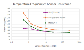
The simulated behavior matches test measurements for higher sensor resistance values, but diverges at lower resistances. When I replace the LMV358A model with a generic spice op-amp, the shape of the response aligns with lab measurements (although offset by a considerable amount):

I'm trying to understand the cause for this, is it a simulation artifact (seems unlikely - I simulated the circuit in TINA with the LMV358A model and got identical results to what I derived in LTSPICE), how to explain the discrepancy to the lab measurements.

