A related question is a question created from another question. When the related question is created, it will be automatically linked to the original question.
If you have a related question, please click the "Ask a related question" button in the top right corner. The newly created question will be automatically linked to this question.
TLV3603: Need help to calculate resistor value for Hysteresis
I'm unsure about what your application is and how much hysteresis you're looking for.
What does the signal look like? Is it truly going to be in the uV range?
In the post you've linked, you're using an INA333 to linearly scale the voltage signal up. A comparator will output a digital high or low depending on if the input signal crosses the reference at the inverting/non-inverting input. Is this the output behavior that you want?
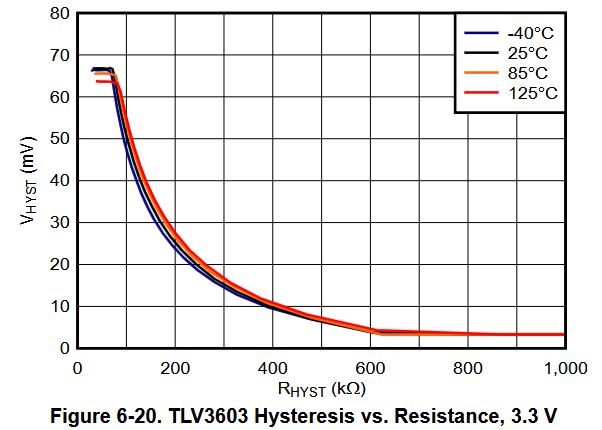
The TLV3603 has the following hysteresis voltage vs hysteresis resistor plot:
In the post you've linked, you're using an INA333 to linearly scale the voltage signal up. A comparator will output a digital high or low depending on if the input signal crosses the reference at the inverting/non-inverting input. Is this the output behavior that you want?
Yes,Amplify output of INA333 will be the input of TLV3603.
The purpose of hysteresis is to mitigate unwanted switching of the output due to noise and/or interference. It's hard to tell at a glance exactly how much you need; it depends on factors like the speed of your input signal, the amplitude of your input signal, and the amplitude of the noise/interference you're expecting in your system. You can create your PCB with the pads for a hysteresis resistor, and subsequently swap the resistor should you end up needing more or less hysteresis. You can start off with ~5mV to 10mV of hysteresis (400kΩ to 500kΩ) and then change the value as needed if you observe any unwanted switching (chattering) of the output.