This thread has been locked.

If you have a related question, please click the "Ask a related question" button in the top right corner. The newly created question will be automatically linked to this question.

BUF634A: Irreversible damage

Part Number: BUF634A
Other Parts Discussed in Thread: LM337, LM317, BUF634

Tool/software:

Hello,

I have implemented the BUF634A component in a headphone amplifier as shown in the attached schematic:

/cfs-file/__key/communityserver-discussions-components-files/14/se.pdf

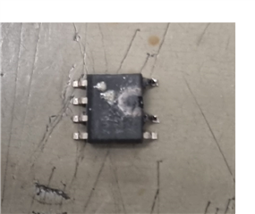
The issue is that, occasionally, in a random and infrequent manner, one of the four BUF634A components completely burns out, as shown in the photo below:

/resized-image/__size/320x240/__key/communityserver-discussions-components-files/14/Senza-titolo.png

- The load I am driving consists of headphones with an impedance between 30 and 100 ohms;

- The power supplied to the BUF634A is generated by linear regulators LM337 (-18V) and LM317 (+18V), and it is stable;

- The temperature of BUF634A stabilises at around 65°.

I ask for your help for understanding where is the problem.

  • Hi,

    Thank you for providing all the details you shared to the issue you are experiencing. I have a couple of questions with the failure. When you see this failure does it occur only when a signal is present, and the circuit is driving a load or is this seen when the circuit is just turned on? If it is fine when just turned on and no signal is driven is the current supply around the expected value for the devices in the circuit? When the malfunction does occur are you able to capture any signals through the circuit. When we see these types of catastrophic failures it sometimes occurs due to instability causing the device to heat up. Do you see this failure when the circuit is in a certain configuration? I saw you had a relay in the circuit, so I was wondering if one specific configuration caused this.

    Best Regards,

    Ignacio

  • Hi,
    the following are my answers:

    the failure occurred three times out of hundreds of hours of testing performed:
    - once it happened immediately as soon as I turned on the device I saw the BUF634 literally catch fire. there was no load connected.

    - the other two times it happened while there was signal and headphones connected to the output. Both times the relay you see in the schematic was energized.

    I have not monitored the current drawn by the BUF634s while they are on without any signal. I will take this measurement and let you know.

    Unfortunately, I cannot replicate the fault in a systematic way. I have tried everything, shorting the outputs during operation, Applying a 100nF capacitive load on the outputs, even so the BUF634s did not fail.

    it occurred to me, however, that during the early stages of prototyping, before making the final PCB I had made a temporary PCB with flying wires, and even that time every time when I turned on the board the BUF634As immediately caught fire. On that occasion I solved it by reducing the bandwidth of the BUF634A then disconnecting the BW pin from the -18V and leaving it floating.
    Then once I switched to the final PCB I saw that on a few occasions the circuit was oscillating so I again connected the BW pin to the -18V eliminating the oscillation and initially found no damage to the BUF634A seeming to work perfectly.

    I hope this will help.

  • Hi,

    Thank you for the additional information. It can be a stability concern if it has been damaged without loading the device as something else is causing the device to burn up. When the circuit is active and driving a signal do you see any signs of oscillations when monitoring the output signal of the circuit? On a separate note, when you do have a circuit working, is there a way you could toggle the relay to see if there is potentially something happening due to the relay specifically. I was wondering if you see any interesting phenomena at the output of the buffer when the relay is being powered on and off.

    Best Regards,

    Ignacio

  • Hi ignacio,

    thank your for yuur feedback.

    I was able to monitor the current flowing on pin V+ (7) when the device is switched on but there is no input signal and it is 8.7mA, both with the load connected and without load.

  • Hi Ignacio,

    I have also tried switching the relay on and off and it does not seem to affect the output of the BUF634A, there is no oscillation here either with load or without load and both with signal and without signal.

  • Hi,

    Thank you for trying the two suggestions. Seeing how the circuit does work and there are no signs of instability it seems like the failure is being caused by something else. Just for some context, can you share how many units you have seen fail as well as the number of PCBs you have used. Have the failures been on a single PCB that a device has just been swapped out until it fails again? The circuit itself looks inherently stable and there are no obvious reasons why it should not work. Can you also share if there is a specific device that is failing? For example, is only U2 failing or has it been random where any given BUF634A is failing.

    Best regards,

    Ignacio

  • Hi Ignacio,

    In total I made 15 PCBs and in three different PCBs the failure occurred.
    In all cases U6 broke and only once also U4.

  • Hi,

    Is there a PCB layout you could share to see if maybe something is causing some issues due to layout? From the schematic I could not find a difference between channels to see why the left channel is failing. Just to confirm, you have seen around 3 devices fail in the final PCB design, correct?

    Best Regards,

    Ignacio

  • Yes, 3 devices in the final PCB design. Please share your mail so I can send you the PCB files