Other Parts Discussed in Thread: LM358
Tool/software:
Dear Team,
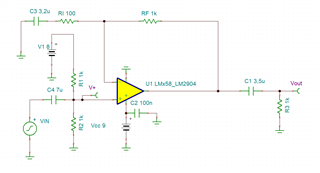
I am trying to build a single supply opamp amplifier using LM358.

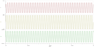
I am expecting a 4.4V Peak to peak out put .But my output is in mV range.
May I know where I went wrong.

Hi HARI,
I am expecting a 4.4V Peak to peak out put .But my output is in mV range.
The output seems to be working good. You have additional capacitor coupled at the output. The input is biased at 4Vdc and AC input signal is riding on the 4Vdc biasing voltage. With the AC signal coupled at output, only AC signal is passed through (capacitor blocks DC).

Single_Supply E2E 12052024.TSC
If you have other questions, please let us know.
Best,
Raymond
Hi Raymond,
My intention is to amplify only the AC content of the signal.I did not want to amplify the DC content.
Here the gain is 11.
The peak to peak amplitude of AC component is 0.4V .
The expected output voltage is 4.4V.(11*0.4).
May I know my understanding is correct or not.
Regards
HARI
Hi HARI,
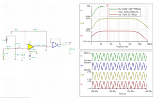
Your generator is only 50Hz, so you need to configure the HPF properly. Here is the modification. The simulation is bit sensitive to AC coupled output (I do not know why - likely due to convergence issues).
The circuit should meet your requirements, if you want to use AC coupled output with 50Hz input generator.

LM358 Single_Supply E2E 12052024.TSC
Best,
Raymond
Hi HARI,
Ok, it seems to be working.
if your operating frequency is 50Hz, then your HPF's cutoff frequency should be configured at least a decade earlier. In this case, it should be below 5Hz. Otherwise, there may be slight input attenuation due to the RC time constant of the HPF. LM358 is not precision op amp, and it may be good enough for your application.
Best,
Raymond
Hi HARI,
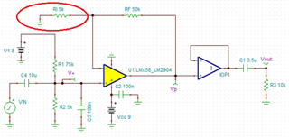
From the simulation, the C2 capacitor is not required, if you configure the input bias voltage correctly - because you want to only amplify the AC signal not the DC signal (place the DC at the mid of the supply rail and riding AC signal at the DC operating point).

If you place the C2 as you simulated, you configured the Vout to the the bias voltage from your voltage divider (~4Vdc). It looks like the buffer configuration at DC.
The R1C2's impedance is a function of frequency. The cutoff frequency for R1 an C2 is approx. 10Hz (fc = 1/(2*pi*R1*C1)). At DC, the C2 is open, that is your buffer configuration. At higher frequency (>100Hz), C2 looks like short, then it looks like my simulation. Between DC and high frequency, it behaves a HPF. You can analyze it using the superposition technique, but it is easier to simulate it.
If you have other questions, please let me know.
Best,
Raymond