Other Parts Discussed in Thread: AMC1200
Tool/software:
Hello:
Pl take a look at the attached schematic.
A signal of 100mV, 1kHz is applied to the inputs of AMC1200-Q1 through balanced RC filters.
U2 amp is biased on the input side by 5V. The output is biased by 5v with an isolated return from the input bias circuit.
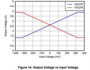
One would expect outputs at pin 6 & pin 7 with common mode DC values of 2.5V.
But we measure 3.8 V on pin 6, 1.2V on pin 7.
And absolutely no signal amplification at all.gmr10d_test_ckt_ti12052024.pdf
What am I doing wrong?
Is it possible that I got the circuit all wrong?
The real application of this circuit is to measure the voltage across Vac nodes when it is replaced by a 1Ohm resistor. U1 is a power converter using UCC2811 controller.
We are measuring, in effect, the input current through the U1 converter, but it must be isolated from the instrumentation side, hence the use of an isolated amplifier.
Any review and comment on this circuit will be highly appreciated.
We just bought a whole lot of this amp from Mouser!
-r


