This thread has been locked.

If you have a related question, please click the "Ask a related question" button in the top right corner. The newly created question will be automatically linked to this question.

LM331: Help me understand the equation provided by the data sheet

Part Number: LM331

Tool/software:

Hello! I am currently doing a project with a group, which uses the LM331 to make a frequency output that varies by voltage. In the data sheet for LM331, the reason why the voltage is proportional to the frequency is described as follows:
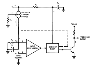
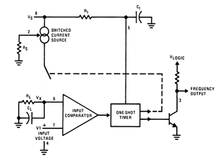
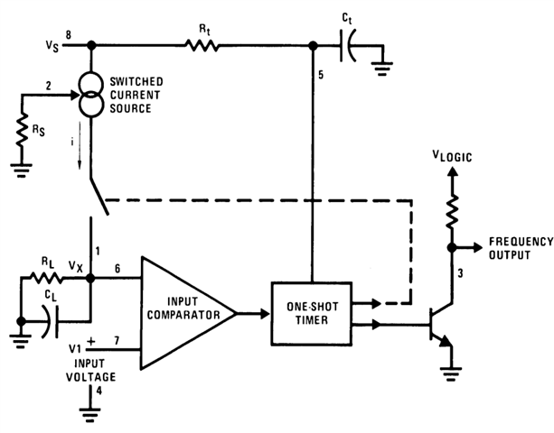
" The current flowing into CL is exactly IAVE = i × (1.1×RtCt ) × f, and the current flowing out of CL is exactly Vx /RL ≃ VIN/RL . If VIN is doubled, the frequency will double to maintain this balance."

First, i dont understand how they assume all of the current i, will be flowing into the capacitor CL. Second i dont understand how these two equations can be set equal. I dont see why the discharging current cant be different from the charging current i. Is this because it is very simplified, or is there something I misunderstand?

  • Hi Martin,

    This part can be a bit confusing! I remember also getting very confused with the functions of this device when I first saw it. Let me help you understand. 

    First, i dont understand how they assume all of the current i, will be flowing into the capacitor CL. Second i dont understand how these two equations can be set equal. I dont see why the discharging current cant be different from the charging current i. Is this because it is very simplified, or is there something I misunderstand?

    The reason the flow is different is due to the circuit changing as a result of the switch in between the switched current source and CL/RL. 

    Let's start with the state when the current flows into CL. I modified the circuit to better reflect this state as shown below:

    This state of operation we will have the source current pushing current into CL, charging it up at a certain rate and will continue to do so till the voltage at Vx is at or above V1 or the input voltage. Once it reaches at or above the V1 voltage, the comparator will cause the switch between the RL/CL and the switched current source to open. 

    For the current flowing out of CL, this occurs when the switched controlled current source is disconnected, see the schematic below. In this state, CL only has two paths to discharge. The first path is through the input of the comparator, which is a very high input impedance path. Usually the amount of current that can flow in it is called the input bias current which is usually between the nanoamps and picoamps range. In other words there won't be much current flowing through it. 

    The second path is through the resistor RL. Relative to the input impedance of the comparator, this is going to be a much less resistive path so the current will flow mostly through this.

    Now this leads to the question of how Vx /RL ≃ VIN/RL. Well the comparator open the switch to when Vx ≃ VIN. We assume that the voltages on both inputs to the comparator are equal then. The current flow of the comparator will thus be represented in ohms law rearranged to be i = V/R. In other words, now the current flow rate is set by whatever the voltage at Vx and RL. 

    Let me know if I was unclear in any part of my explanation. 

    Best Regards,

    Robert Clifton

  • Thank you for a well written out reply! This clears a lot up, but some things I still do not understand. When the current is going from the "current source" and into CL, why doesnt some of the current pass through RL? is this picked to be very high? and mostly, when they write  "If VIN is doubled, the frequency will double to maintain this balance", does this imply that the current in state 1 into CL is equal to the current flowing out of CL in state 2, or at least that they are proportional?

    Thank you

    Martin

  • Hi Martin,

    Thank you for your kind words. 

    When the current is going from the "current source" and into CL, why doesnt some of the current pass through RL? is this picked to be very high?

    This is poor wording on both mine and the datasheets part. The current is going through RL and CL. Mostly through the resistive element. What's more important from the capacitor is the voltage is "charging" the capacitor to the new voltage potential. 

    "If VIN is doubled, the frequency will double to maintain this balance", does this imply that the current in state 1 into CL is equal to the current flowing out of CL in state 2, or at least that they are proportional?

    They are independent of each other. The current that is seen in state 1 (switch is closed) would be very steady compared to the discharging of the capacitor seen in state 2. The output would look more akin to a sawtooth voltage signal. 

    Best Regards,

    Robert Clifton

  • I think this clears most up, thank you!