This thread has been locked.

If you have a related question, please click the "Ask a related question" button in the top right corner. The newly created question will be automatically linked to this question.

OPA172: TIDU765_Facing issue with arrived component values for less sensitive microphone

Part Number: OPA172
Other Parts Discussed in Thread: JFE150, OPA1656

Tool/software:

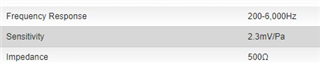
We've considered the TIDU765 reference design & trying to adapt the circuit as per the microphone specification. The microphone that's readily available(CB Cobra microphone) for our configuration is having less sensivity(-66dB) compared to the reference mic(-35dB) that's been considered in the reference design. 

Also, I've increased the maximum SPL from 100dB of reference design to 135dB because this is the max. human sound. 

The final values are largely deviating from the reference design so I'm worried whether I'm making any mistakes so seeking your help. I've attached the calculation document where it has 2 vertical sections. 1-> Reference calculation to compare 2-> Calculation w.r.t our configuration. Microphone_PreAMP_Components_Calculation.pdf

Actually, the reference design has already been implemented in one of our project where we're facing 2 issues: 1. Clicking noise while switching on the microphone 2. Idle humming noise. So don't wanna take risk with implementing random reference values. 

  • Hi Santosh, 

    One thing I noticed in your calculations is that VCC is 3V. Is that correct? Do you know what the minimum drain to source bias voltage is for the JFET internal to the microphone? As an example, you can see below that there are two modes of operation for a JFET; the linear and saturation regions. You want to ensure that you are biasing the microphone with sufficient VDS voltage to operate in the saturation region. The example below is from our JFE150. 

    You also want to bias it with enough IDS current such that you get lower noise. For example, you can see the best bias point for our JFET is around 2mA. Currents greater than 2mA provide diminishing returns. Going too high actually will make it worse so it is a balancing act. All that to say, it is important to know the requirements for the microphone bias points. 

    It is hard to say how much variation there is for the JFET internal to the microphone. We recently released our own JFETs and the gm (gain) variation can be as high as 30% (very conservative estimate). I suspect the microphones internal JFET is at least that. If you are willing to add feedback to the circuit for predictable closed loop gain such that you don't need to rely on JFET variation you may tweak the design as shown in my application note below. I suspect this is more of a biasing issue than anything and you may not require the feedback. I have provided the information below for additional resources and options.  

    Here is the JFE150 app note. Of course the JFE150 wouldn't be in the design as you already have a microphone with a JFET internal to it. 

    https://www.ti.com/lit/an/slpa018/slpa018.pdf?ts=1733888090797

    The drawback is you will need a large cap in the source of the JFET. The benefit is the gain is set by two feedback resistors and is stable and predictable. I have detailed out all the calculations for each corner frequency within the app note. I have also created an evaluation module for the design. 

    https://www.ti.com/tool/JFE150EVM

    I hope this information is useful. Let me know if I can be of further assistance. 

    Best Regards, 
    Chris Featherstone

  • Hi ,

    Thanks for sharing your detailed application note here. 

    Vcc=3.3V which is generated by LDO. 

    The microphone that we're utilizing is a dynamic microphone(has significantly less sensitivity compared to condenser) which doesn't require any supply voltage so there won't be any internal JFET(Disassembled the microphone internals & didn't notice any JFET over there). 

    Here are the specs of microphones that we're using

  • Hi Santosh, 

    The design below is for the electret microphone where R1 to the supply biases the JFET. Since your microphone does not require this biasing; applying biasing may cause problems. I am not sure how your circuit is wired up. Using a design such as the one in my app note should work because the mic signal is applied at the gate of the JFET. Alternatively you can just use an op amp such as the OPA1656 circuit for the microphone if you need a single ended input. The dynamic microphones require a much louder sound source than the electret. Do you need the design below for your application? 

    Best Regards, 
    Chris Featherstone