A related question is a question created from another question. When the related question is created, it will be automatically linked to the original question.
If you have a related question, please click the "Ask a related question" button in the top right corner. The newly created question will be automatically linked to this question.
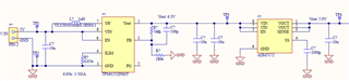
Vin: I created a circuit that boots from 5V to 6.3V and converts it to 5V with a regulator, but when I connect a 100mA load, Vout drops to 5.3V. Why can't it maintain 6.3V?
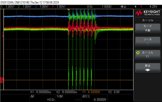
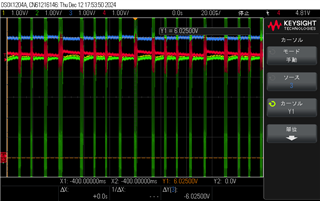
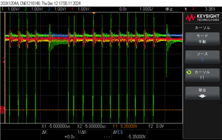
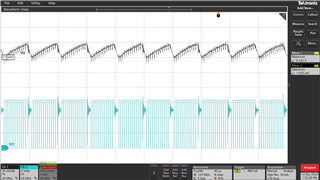
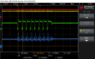
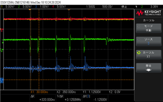
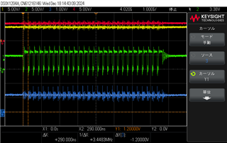
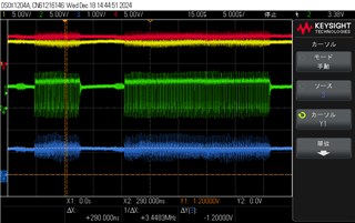
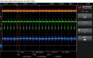
Hi Travis The waveforms are Ch1: Vin, CH2: SW, CH3: Vout, CH4: regulator, 5V. The first panel is at no load The second panel is at 30mA load The third panel is at 100mA load Vout is 6.3V at no load 6.0V at 30mA load 5.3V at 100mA load The sine current is set to 1500mA.
I tried the same condition on EVM and it works normally. Can you catch SW, Vout, FB and ILIM pin voltage on your bench and catch waveform again. Open 20MHz band width limit on all channels to reduce noise.
The IC current limit does not support 1.5A load. Your waveform shows the IC is still in light load condition. So I suggest focusing on previous waveform. Can you catch SW, Vout, FB and ILIM pin voltage waveform on your bench?
The modulation circuit is working normally. The Toff becomes longer because Vout drops very close to Vin and volt-second balance is hard to be established. I think the root cause is from the FB divider part. The FB voltage is still around 1.2V on the second waveform when Vout drops to 5.3V. According to the divider ratio, the FB voltage should be 5.3V*180k/(768k+180k)=1.006V while the waveform shows FB is above 1.125V line.
Can you remove feed forward capacitor and try again. Or is there some other circuit around FB divider that's not shown in the schematic.
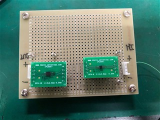
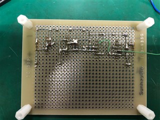
Honestly, I cannot tell why your divider is not dividing Vout by the expected ratio. I'm applying the same 768k, 180k and 100pF divider as your schematic and the output is correct as expected. Can you share layout so that I can check it? Also, please apply an EVM and see whether the same IC works normally on EVM.
Switching regulators are very sensitive to parasitic inductance on layout and cannot work normally without proper layout. Please apply for an EVM if you need to evaluate the performance.