This thread has been locked.

If you have a related question, please click the "Ask a related question" button in the top right corner. The newly created question will be automatically linked to this question.

INA333: INA333: Hardware Design with PT1000

Part Number: INA333
Other Parts Discussed in Thread: TIPD170, , LM7705

Tool/software:

I made this design. In this design, I aim to measure temperature using PT1000 resistor. The analog input range of the processor is between 0V and 3.3v. 

While designing “www.ti.com/.../TIPD170 I took this application as a reference.

The output of this circuit is between -40 degrees 0.35V / +80 degrees 0.82V. But I want to adjust the mV output between these temperatures to be 0V at -40 degrees / 3.3V at 80 degrees.

What do I need to change in the circuit? 

How should I follow a path for design change?


  • Hi Gulbahar, 

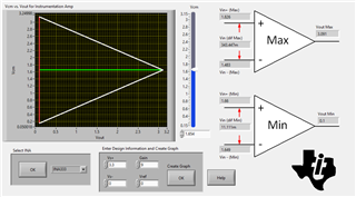
    The instrumentation amplifier output swing cannot swing all the way to the rails, please refer to the characteristic table and typical plots. We also have the Analog Engineer's Calculator (https://www.ti.com/tool/ANALOG-ENGINEER-CALC) to input your specific application conditions to see what the input and output swing limitations are. 

    In single supply +3.3V, with a Vcm at midsupply, your max output swing range is approximately 3V. 

    If you need 0V included in the output, then the supply voltage will need to be changed to dual supply, but your upper end of the output swing will still be limited regardless of what you choose for your supply voltage. 

    Regards,
    Ashley

  • Hi Ashley,

    How can I do dual supply with INA333? I don't fully understand, can you suggest any source or drawing?

    Also, I cannot go above 3V with this design. Can you suggest me another opamp and source that I can read between 0V and 3.3?

    Regards,

    Gülbahar

  • Hey, Gulbahar, 

    By dual supply, we mean you need a negative V- supply voltage to allow for enough output headroom to output a 0V signal. 

    Most customers do not necessarily have a low voltage bus with a negative voltage. A solution to this can be to use the LM7705 connected to V- of the INA333 to provide a slightly negative bias.

    This will solve the  output swing problem to 0V, but as Ashley mentioned above, you will still have problems outputting 3.3V. The only way to reliably swing to 3.3V is to use a supply which is large enough to allow for sufficient swing. The Analog Engineers Calculator will allow you to confirm all of these swing values. If we look at the existing 3.3V supply, you can see that we can only output 3.091V with mid-supply common mode. This means we will likely need to increase out V+ supply to at least 3.6V to reliably output 3.3V. 

    The easiest and most reliable method to solve this problem involves changing the desired swing range of your INA. Rather than use 0 to 3.3V scale, a more sound design will use something like .3V to 3V. Yes, this will effectively give up resolution in the ADC, but you will not have to worry about non-linear operation for the INA. Additionally, you will be able to detect fault conditions in the event the RTD is disconnected from the INA. Finally, it can be nice to have enough extra sensing room in the event the sensor temp range is slightly exceeded: 85C, or -45C operation. 

    Please let me know if you have any questions.

    Best,

    Jacob