LMC6482: Single-Supply Buffer Configuration - Positive Rail Issue

Part Number: LMC6482

Tool/software:

In my application the amplifier mounted on PCB is powered in single supply mode 0V-10V, in buffer configuration
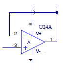
When IN+ is 10V the output is 9.55V. The output does not reach the positive rail.

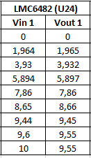
Changing the input voltage from 0V to 10 V I obtained the following  graph of Vout 
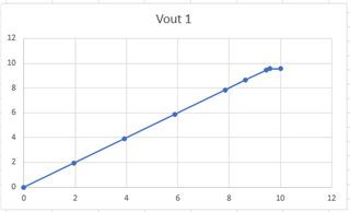
As you can see if Vin excedees the value of 9.55V the output remains at 9.55V.

Why I can not reach the positive rail? 

And how can I solve this problem?

Thanks in advance,

Emanuela

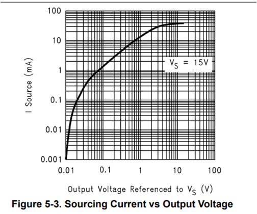
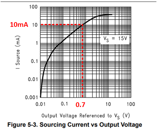
  • The reachable output voltage depends on the output current (see figures 5-3/5-4). What is the load?

  • Emanuela,

    I agree with Clemens.  What load and power supply are you using?  Also, what power supply are you using?  I assume you are using a 10V supply, but if not we may need to look for other problems.

    Best regards, Art

  • Hi everyone,

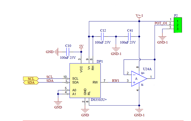
    below is how the device is used

    I am using a 10V supply.

    When IN+ is 10V the output current is 10.2mA, with no load.

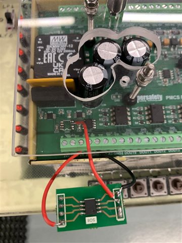
    By dismantling the component from the PCB and mounting it externally, in the same conditions on the Output pin I measure 10V.

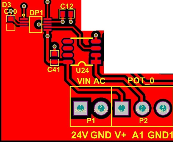
    Why? Could this be a layout problem? Below the layout section I used

    Thanks in advance,

    Emanuela

  • Emanuela,

    • You say: When IN+ is 10V the output current is 10.2mA, with no load. I think you mean the op amp output current.  The op amp output current is the current that flows out of the output pin of the op amp (pin 1 in this case).  For any unloaded op amp the output current is 0A.  Thus, saying the op amp output current is 10.2mA when the amplifier is unloaded doesn't make sense to me.
    • Assuming the output current is 10.2mA, the output swing should be limited to about 0.7V from the supply rail or 9.3V max output.  You actually measured better swing than that.  This seems like normal behavior.  Use figure 5.3 below:  
    • I looked at your layout, and I looked at your attached proto board.  They both look correct and identical.  The PCB version should actually preform much better because it has local decoupling capacitors.  If the version on the small PCB works better than the load current is probably different.  
    • All amplifiers have an output swing limitation.  In summary, this means that the op amp output will not be able to go all the way to the power supply voltage.  In some cases the output swing limitation can be several volts from the rail.  Different amplifiers will have better or worse output swing limitations.
    • You really need to set your op amp power supply higher than the maximum output swing limit.
    • Op amp precision labs output swing videos covers this topic.  Also Op Amp Input and Output Swing Limitations cover this topic in detail.  I suggest reviewing this content.

    best regards, Art