- Ask a related questionWhat is a related question?A related question is a question created from another question. When the related question is created, it will be automatically linked to the original question.
Tool/software:
Hello,
I am considering a circuit that can control CC by adding an external circuit to the TPSM63610.
The application note I am referring to is below.
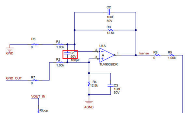
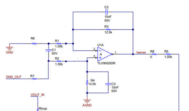
I am using TLV9002 for the CC control circuit because it is used in this application note. It is used in Figure 3-1.
In the circuit I created, the switching frequency is unstable.
I suspect that this is because the phase margin of the differential amplifier circuit used in the CC circuit is low. Is there a way to increase the phase margin in the differential amplifier circuit?
I think it is also affected by noise, so I would like to slow down the responsiveness and increase the phase margin.
Best regards,
How to Implement a Simple Constant Current Regulation Scheme to a PCM Based Buck