This thread has been locked.

If you have a related question, please click the "Ask a related question" button in the top right corner. The newly created question will be automatically linked to this question.

OPA547: Current detection issue

Part Number: OPA547

Tool/software:

Hi expert,

My customer is evaluating OPA547 in Multimeter and met below detection:

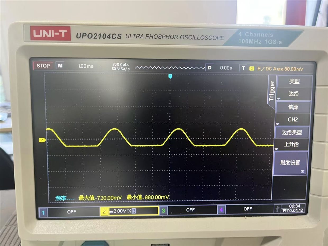
  • The OPA547 in Multimeter is used to detect AC current, the detection result is unstable as below video show. The detection result is accurate (about 200mA) in the first two seconds and the waveform is normal sine signal as below first waveform show. But the detection result would drop to about 150mA after two seconds and the waveform is abnormal as below second waveform show.\

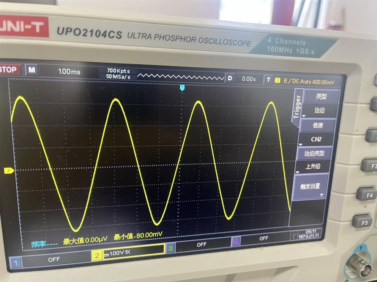
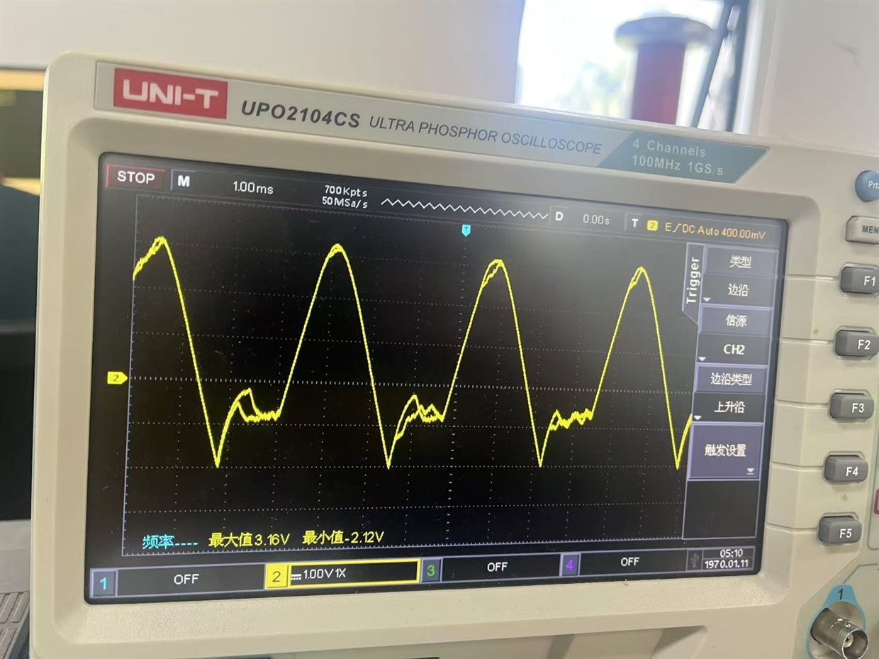
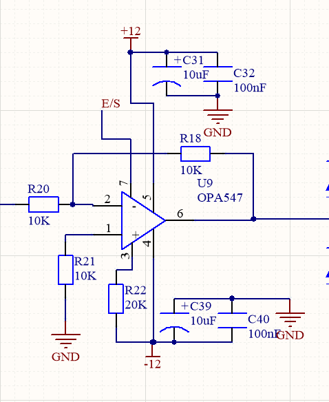
  • Besides, Vin=3.6VAC(270Hz), Rload is 10Ω resistor, the V+ of OPA547 is 12V and the V- of OPA547 is -12V, RCL of OPA547 is 20kΩ.

Best Regards,

Ryker

  • Hi Ryker, 

    Thanks for helping support this design. 

    So the customer is trying to use the OPA547 inside multimeter design for AC current sense, correct? 

    Can we see the schematic for this design?

    The RL of 10ohms should be fine with a 3.6V Pk AC sine wave with 270Hz frequency and +-12V supply. 

    What is the yellow waveform? Is this the voltage output of the OPA547, or the current input being measured by the OPA547?

    The clipping on the negative side of the sine wav is interesting. Can the customer monitor the E/S pin to make sure the device is not entering thermal shutdown?

    Thanks,

    Jacob

  • Hi Jacob,

    Please refer to my input:

    • This issue only appears when the output current (RMS) bigger than 100mA. And disappears when the output current less than 100mA. It seems the reason is temperature rise, but R&D measured the temperature of OPA547 is about 50℃ and the E/S voltage is bigger than (V-)+2.4V (show as below)
    • Yes. Customer is trying to use the OPA547 inside multimeter design for AC current sense.
    • The OPA547 schematic as below: Input voltage (3.6VAC/270Hz) is connected to R20 and OPA547's Pin6 is connected to 10Ω resistor. 

    • Yes. The yellow waveform is the voltage output of the OPA547. 
    • Please refer to the E/S waveform (E/S-GND) as below: The first waveform is the first two seconds with normal current sense. The E/S waveform is strange after two seconds as below second waveform show.
    •    
    • It isn't useful to connect the E/S to GND directly. We also tried to remove U13(refer before schematic) and R52, and then connect the E/S to GND (The issue still exists even if the E/S voltage keeps stable 0V).
    • We also have used different OPA547 and board to test, but the issue still exist.

    Best Regards,

    Ryker

  • Hi Ryker, 

    Thank you for details here, this is helpful for me. 

    The E/S pin changing voltage and this problem only occurring during sustained high current operation better supports the idea that this could be thermal related.

    What package are you using for the OPA547? Are you connecting the thermal tab to the PCB, or a heatsink?

    This device will consume about 1/4W of power just from Iq flowing into the device, and 3W during the peak of the sine wave. 

    Best,

    Jacob

  • Hi Jacob,

    Customer uses TO-220 package and connects a heatsink. R&D measured the temperature of OPA547 is only about 50℃. And the issue can't be fixed even if they use a fan to dissipate heat. Do you have some suggestions to resolve this issue? Thanks.

    BR,

    Ryker

  • Hi Ryker,

    Thank you for the additional details.

    Here is my thought process:

    1. This circuit works for first few seconds of operation. This makes me believe this is not a current limit problem. Math also confirms that the RCL should work well for the selected application. 

    2. After a few seconds of perfect operation, we see problems. This means there is some time constant which is altering the performance of the amplifier. Interestingly, this problem appears to only influence operation at the high voltage portion of the sine wave: high instantaneous power for amplifier. 

    The E/S pin changing makes me still believe this could be power related. 

    Did the customer use thermal paste to attach the heatsink to the TO220 package? Is the 50C being measured at the heatsink outer surface?

    Here is a good way to confirm that this may be thermal related. How long does the customer have to wait before the abnormal operation goes away (Operates like waveform 1)? Is this solved by power cycling the device, or something more like waiting a longer period of time without high current operation?

    Thanks,

    Jacob

  • Hi Jacob,

    Please refer to below update:

    • Customer has confirmed that they need to wait 2-3 seconds, and then abnormal operation goes away. So, this can be solved by waiting 2-3 seconds. It seems is thermal related, but the mArms is only about 200mA, why it would cause over temperature?
    • They didn't use thermal paste to attach the heatsink to the TO220 package, I will let customer try to use thermal paste. The illustration and PCB layout as below. Please help to check if there is any problem or give some suggestions. Thanks.

    Best Regards,

    Ryker

  • Hi Ryker, 

    Thanks for the additional details. 

    C39 looks pretty burnt, is this any concern? I believe this is our V+ decoupling capacitor.

    Yes, it would seem like the heatsink is enough to cool the power amplifier, but there are some important things to remember here:

    1. we are using relatively large supply rails: +-12V. This mans that even if the amplifier is turned on with no load current, we are burning .25W in the amplifier. 

    2. Trace resistance and other factors can cause losses which otherwise may not have been simulated for. 

    3. The thermal shutdown is based off of internal die temperature, not heatsink temp. This means that large instantaneous power dissipation can cause this junction temperature to rapidly increase. In the case of the heatsink, the poor thermal conductivity between the TO-220 package and the heatsink can absolutely cause problems. It seems counterintuitive at times due to the heatsink size, but realistically, the package and heatsink mounting surface are imperfect surfaces which are only using a small surface area for contact patch. With the thermal paste we will significantly improve this thermal junction.  

    Thanks,

    Jacob