Other Parts Discussed in Thread: TLC3702
Tool/software:
Hi,
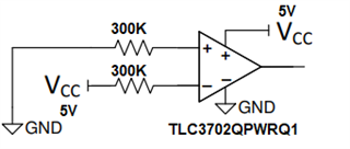
To clarify in the very beginning.We are using a spare TLC3702QPWRQ1 in below configuration. As per this link.
Config 1

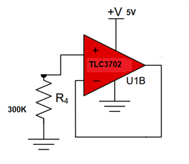
Just for our curiosity and better understanding of comparators, we were discussing below circuit with negative feedback.
Config 2

And we tested these circuits as well.
Our observations were:
1. Both circuits have outputs as 0V.
2. Config 2 has around 100uA more supply current (Icc) than Config 1. No output switching/oscillations observed on the output of Config 2.
We would like to know the reason behind this increase in Icc.
Is any component inside TLC3702 going in active region, which ideally should be in saturation/cutoff?
We understand config 2 is not a recommended circuit for a comparator.


