This thread has been locked.

If you have a related question, please click the "Ask a related question" button in the top right corner. The newly created question will be automatically linked to this question.

TLV3801: 0mV and split power supply comparator option

Part Number: TLV3801
Other Parts Discussed in Thread: TLV1871, TLV3811

Tool/software:

Hi Team,

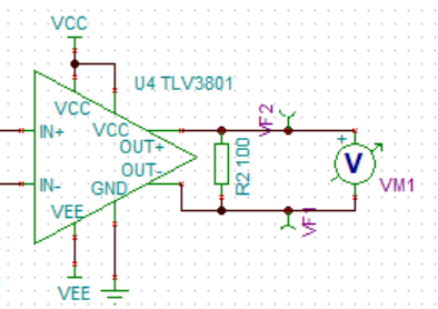
I have been so far using the TLV3801 comparator for my project. But I now require a comparators with the following criteria; 0mV hysteresis and input split power supply. TLV3811C looks to be a great candidate but it doesn't have an input split power supply. The idea is that I need to compare a 500MHz high-speed ac-coupled signal with 0V/ground. Could you propose any components/ circuits that could be useful for this?

  • As far as I know, the only other comparator with split supplies is the TLV1871, which is too slow.

    If the input is AC-coupled, couldn't you bias the TLV3811‍C's input voltage higher?

  • Thanks for your prompt reply.

    May I know if you could suggest an optimal way of biasing the high-speed signal using just passive components without affecting the speed at all? I don't want to use any additional FDA or other IC components for the same. On an additional note, I have a very low noise LDO of 2V which can be used as the bias voltage.

  • Typically, you'd use a resistor divider with a voltage in the middle of the common-mode voltage range.

    Do you have any requirements for termination impedance?

  • Hi,

    Yes, the ac-coupled output of MAX40660 https://www.analog.com/media/en/technical-documentation/data-sheets/MAX40660-MAX40661.pdf (image below) needs to be compared with the voltage of 2V from a LDO (since it's ground is not possible).

    Only one of the differential pair of MAX40660 would be used, let's say OUTP and the other OUTN would be terminated with 50ohms to ground after the ac-coupling capacitor. Both traces will be routed as single-ended co-planar traces.

    To maintain signal integrity and avoid reflections, I believe 50ohms termination is required after the 0.1uF coupling capacitor. Is it possible to just use a pull-up resistor with 50ohms to 2V for ac-coupled the signal output to be connected to the input (non-inverting input) of the TLV3811C's? The other input (let's say inverting input) of the comparator can also be pulled-up to 2V with 50ohms Would this be enough or do we need any other circuit?

    The single-supply voltage can be around 3.3V and the maximum peak-to-peak output signal of MAX40660 is around +-150mV with respect to ground.

  • A single pull-up or -down resistor has the correct impedance. (This is called parallel termination.)

    But you would not need the 2 V supply with Thevenin termination, i.e., a resistor divider (whose impedance can be computed as the two resistors in parallel).

    As far as I can see, the MAX40660 datasheet does not guarantee a fixed output common-mode voltage, so it might be necessary to create a proper differential receiver.

  • Hi Shine,

    Could you please provide a block diagram of what you're trying to achieve? In addition, why is a comparator with separate supplies necessary for your application?

    Thanks,

    Ho

  • Hi Siu,

    Here's a very simplified block diagram of what I'm trying to achieve with TLV3801 comparator.

    This configuration with a split power supply means I can compare the signal with 0V (ground) that devoid of any additional need for power supply and also ground would be more stable voltage reference.

    Hi Clemens,

    The MAX40660 datasheet mentions that it can also be used as a single-ended output by having the used output pin ac-coupled and terminated (page 15). In that case can I just use a 50ohms pull-up (parallel termination) or a Thevenin termination with appropriate resistance values to give 50ohms at the ac-coupled output pin I need to match the impedance and ac-couple, terminate with 50ohms the other unused pin?

  • Shine

    That is correct.  We would recommend termination of the other terminal with the same resistance value.  We actually characterize our devices using split power supplies where GND is the reference for the reasons you mentioned above.  We simply shift the power supplies to test the different common mode voltages.  Even though one terminal is at GND, we still connect to ground through a termination resistor value of 50 ohms.

    Chuck

  • Hi Chuck,

    Thanks for the reply. I also wanted to point out that the TINA spice macro of TLV3801 doesn't not work with any split voltage values less than +/-2.5V contradicting the datasheet min and max values (Vcc- Vee). I tried with +/-2V which is what I need in the system and the macro always shows pV of output. Could you confirm it's a macro issue and I haven't missed anything from my side? I used the TINA design reference file from product website from TI.

  • You’re very welcome Shine and thanks for your persistence and patience  

    From the recommended operating conditions, VCC with respect to ground must be greater than 2.4V. So +/-2v is not allowed. If you can increase VCC to 2.5v, it’s ok to leave VEE at -2v  

  • Hi Chuck,

    Thanks for the confirmation for single power supply. I was mentioning about the split power supply, shouldn't it ideally work with +/-2V for Vcc and Vee respectively meaning Vcc-Vee = 2V-(-2V) = +4V > 2.7V. But the TINA macro doesn't allow it, could you look into it.

  • Please read the table I inserted. VCC with respect to GND. You’re only looking at VCC- VEE

  • Hi Chuck,

    Yes, I was mentioning about a different use case where I need "split power supply" using TLV3801. I was confirming that when using TLV3801, and I need split power supply operation, I could use Vcc = +2V and Vee = -2V? The table you have inserted says it's possible as Vcc - Vee = 4V > 2.7V (the second row in the table). The TINA macro from TI only works with +2.5V and -2.5V even in split power supply configuration, could you confirm this?

  • Hi Shine,

    I'll need some time to take a look at the internals of the model. Please give me some time to confirm the issue and investigate. I'll reply to this post when I have updates.

  • Hi Shine,

    Even with split supply operation, you need to satisfy TWO conditions:

    First, VCC - VEE > 2.7V. You have VCC = 2V and VEE = -2V, so VCC - VEE = 4V. You are satisfying the first condition, so you are fine here.

    As Chuck was saying, there is a second condition you need to satisfy: VCC - GND > 2.4V. You have VCC = 2V and GND = 0V, so VCC - GND = 2V. This is the condition that is not satisfied, which is why the model is not having a full swing to indicate this error.