- Ask a related questionWhat is a related question?A related question is a question created from another question. When the related question is created, it will be automatically linked to the original question.
Tool/software:
Hi Experts,
We have query from user about this appnote:
Figure 5-1 (page 8):
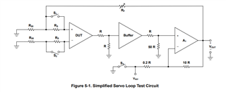
Question on what kind of test circuit is TI using for their Input offset voltage measurements depending on the Common mode voltage of the Op amp.
His concern, if understand correctly, is that by changing the common mode voltage at the inputs of the device under test the Vcm will show at the output of the device alongside the amplified offset voltage. Then to get the Input offset voltage I would have to subtract the set Vcm from the output. Which brings a problem which don't know how to do. Also know that the Vcm of the device can be changed by symmetrical power rails.
Curious how does TI perform this test.
Thank you for your assistance.
Regards,
Archie A.