This thread has been locked.

If you have a related question, please click the "Ask a related question" button in the top right corner. The newly created question will be automatically linked to this question.

INA740B: Power Monitor Measurement Issues

Part Number: INA740B
Other Parts Discussed in Thread: SYSCONFIG,

Tool/software:

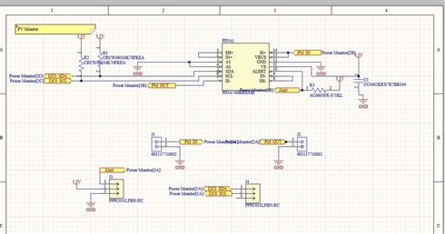
Hi, I'm using the INA740B digital power monitor for a university project. I have it soldered to a test board and a 3.3V LED is being powered through it. My power supply says the LED at 3.3V is drawing 0.014A and consuming 0.044W. However, the results I'm getting through the power monitor are 2.825V, 0.0072A, and 0.0202W. For programming the power monitor, I used the C code generated through TI SysConfig and have it running on a Raspberry Pi Pico. The code is in the zip file attachment. The power monitor connects via I2C just fine and some data is being read, although it does not seem to be accurate. My thinking is it could be 1 of 4 things:

  1. This might be too low of a power level to be accurately measured by the device.
  2. I'm not reading one of the registers correctly (current, voltage, power).
  3. The ADC conversion time needs to be adjusted.
  4. The circuit is wired incorrectly or there is an issue with the microcontroller.

Any advice or suggestions with this issue are greatly appreciated.

 Power_Monitor.zip

  • Frank,

    Thank you for your patience. Due to the U.S. holiday, the team is out of the office, but will reply when we return on Tuesday, 1/21.

    Louis

  • Hey Frank,

    I am looking over your question and will respond soon.

    Sincerely,

    Peter

  • Hey Frank,

    Welcome to the forum.

    Most likely this is simply an offset limitation of INA740B. The offset is rated up to +/-62mA and you are measuring down to 14mA, so offset error will be an issue. 

    Would you please send a complete schematic showing all other loads on the 3V3 line, connections of INA740B, etc?

    What is the instrument showing the 14mA readout?

    Sincerely,

    Peter

  • Hi Peter, 

    Thanks for your response. I've attached the schematic and the PCB layout for the test board we've made. 

    It does appear that we may be running into the issue of the +/-62mA offset. I'm using a separate microcontroller (Arduino Uno) 3.3V power for VBUS (connected to J1 in our schematic) and have a 25Ω load connected to J2. The idea was to draw around 130mA, which is above the 62mA offset. Below is a chart of what I measured with the power monitor and what I measured with a handheld multimeter:

    No load -

    Power Monitor = 2.83V, Multimeter = 3.31V

    25Ω resistor connected -

    Power Monitor = 3.18V, Multimeter = 3.61V

    Power Monitor = 0.04 to 0.11A, Multimeter = 0.17A

    Power Monitor = 0.01 to 0.37W, Multimeter = 0.6137W

    So it appears that connecting the resistive load causes VBUS to rise to 3.61V (and the power monitor is measuring about 0.4V lower than the multimeter). The current and power readings are jumping all over the place, at there highest point they are still a bit off from the actual reading. 

  • Hey Frank,

    I’m looking this over and will respond within 24 hours.

    Sincerely,

    Peter

  • Hi Peter,

    Just wanted to update you that we were able to resolve our current sensing issue with the power monitor. It appears that it was a soldering issue and the IN+ and SH+ pins were not properly connected.

    However, we are still noticing a discrepancy between the VBUS measurement from the device and a multimeter. We attached a 1.5Ω power resistor to a Keysight lab bench power supply (set to 3.3V) and are reading ~2A on the power monitor. However, for the voltage the multimeter reads 2.6V and the power monitor reads 2.3V. We are testing further to determine if there's an issue with our power supply or resistors, but is it expected to see a small voltage drop from the shunt resistor in the power monitor?

    Thanks,

    Frank 

  • Hey Frank,

    When measuring VBUS directly with a multimeter, I would make sure to probe right at the VBUS pin/pour and the GND pin/pour, as close as possible to device VBUS and GND pins. Perhaps there could be difference in ground potentials. The shunt voltage drops from IS+ to IS- should not be very large.

    Please provide this measurement with locations of where you are probing on board.

    Sincerely,

    Peter

  • Hi Peter,

    Apologies, it appears this issue was also resolved by resoldering the component. Thanks for you help, I will mark this as resolved.

    Thanks,

    Frank