Tool/software:
For the noise performance of an amplifier for high impedance sources not only the 2.3nV/sqrt(Hz) performance but also the current noise density is important. For a Rs=1MOhm source resistance the induced voltage noise density from the JFET input current density is:
Vnd(Ind-JFET)=1e6*1.5e-12=1500nV/sqrt(Hz)
The voltage noise density of the source resistance themselve is:
Vnd(Rs)=4kT*1Mohm=sqrt(1.66e-20*1e6)=128.8nV/sqrt(Hz)
The BUF802 would be a bad choice as it have a nois figure at Rs=1MOhm:
NF=20*log10(1500e-9/128.8e-9)=21.3dB
If we look at the shot noise of the leakage current:
Ind(Ileak)=sqrt(2*q*Ileak)=sqrt(2*1.6e-19*3e-12)=0.98fA/sqrt(Hz)
The number from the shot noise is more than 3 orders lower than the sepcified number of the BUF802 JFET input.
I looked also at this post:
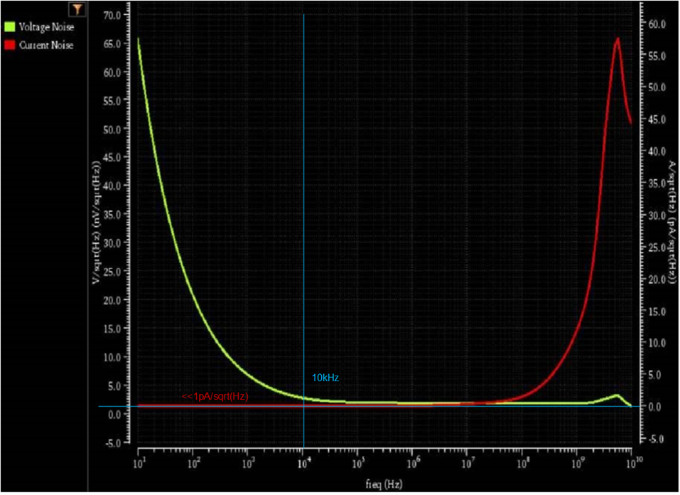
where the customer as for the current noise. TI support also post a noise simulation plot, unlucky with very low resolution and without vertical markers.
The current noise plot is not easy to read below 0.5pA/sqrt(Hz) and it should be mention that the voltage noise to the left and the current noise scale to the right do not match there zero axis. I am not shure what is going on here but the current noise density of the JFET seams very bad and also the 1.5pA/sqrt(Hz) could not be read on a input noise plot from another post. Anyway both make the JFET for 1MOhm sources look bad.
Hello Mr Franke , Dr, Alan Victor
I apologize for the lack of clarity in the axis and the steady state values and I am getting in touch with the designer to get this fixed and share with you the marked Log Y axis values for better readability.
I will get back to you on the values of current noise as a function of frequency. I do understand your concern and calculation. Usually scopes will not give noise numbers for 1Mohm mode hence we did not worry about getting noise low for 1Mohm source impedance.
Since the Input current noise is increasing as frequency increases , may I know up to what frequency are you looking at ?
On a side note we are designing BUF803 , a new version of BUF802 for improved S11 performance and perhaps we can relook at reducing the current noise to an acceptable level Can we have a quick email exchange if possible to ensure your required improvement requests are met. My email id is shree@ti.com
Hi Shreenidhi,
"Usually scopes will not give noise numbers for 1Mohm mode". Experience scope user do not care about paper numbers. Instead they look how general circuit solution are implemented and finally measure if it will major affect the application. As it will differ between manufactures you will have good or bad experience with new applications.
I would guess that the 10kHz 1.5pA/sqrt(Hz) is a typo as any JFET would be better. True, the current noise density rise with frequency as a second contribution beside the leakage. This mean that the current noise of the drain-source is divided by the current amplification similar to a bipolar. The current gain goes to infinite for DC. But where is the transistion depend on Gm/Cgs. So better is to plot like TI did it but with the correction.
It is nice to hear that the BUF803 get closer to customer satisfaction. I would have the following suggestions:
1. Allow for independent voltage definition of the internal buffer clipping voltage definition and the ESD-diode connection. I know you need 4 pins, i did not check if it will fit and be pin/function compatible.
2. Specify the AUX dynamic range. This is useful because in a overdrive situation you will match the clipping value for the DC loop drive input AUX to the external clipping you have to apply on the feedback integrator. Otherwise overdrive recovery in the DC loop will be catastrophic. A more clever way would be to match the AUX clipping to a resistive stop for the integrator.
So i wait for the current noise clarification.
Hello Reiner Franke Dr, Alan Victor ,
Please find , current noise of BUF802 attached.
Thank you Shreenidhi,
but i still puzzling with the 23.04fA/sqrt(Hz). The circuit configuration, if true only connect 2 diodes and the JFET input. The datasheet state 3pA leakage current which give:
1. sqrt(2*q*Ileak)=sqrt(2*1.6e-19*3e-12)=0.9798fA/sqrt(Hz)
2. sqrt(4*k*T/10e6)=sqrt(1.66e-20/10e6)=49.743fA/sqrt(Hz), Noise from the parallel connect 10MOhm resistor if the plot show the application noise
3. Ileak=(23.0359e-15)^2/(2*q)=1.6583nA, if i use the plot and assume noise is coming from leakage. But the leakage do not exceed 200pA at 95°C ambient.
If you get a circuit configuration and some numbers they relate. These numbers do not relate. So either the circuit is different or some of the numbers are incorrect.
I am working for 33y as an analog IC designer and also cover application designs. Checking numbers is the bread and butter in IC design to sniff out misconceptions and issues in simulation setups as they being costly and hurting long time.
Btw the plot have a remark "confidential". This is a public forum.
I will look at the BUF802 model later for more info.
Best regards, Reiner
Hello Reiner, I really appreciate your feedback and the time taken by you to look into this.
I agree with you on the numbers not lining up.
We found some issues in our simulation workbench and were able to solve the issues and generate the new current noise plot. For this plot the circuit is configured similar to the application section BUF802 composite loop. please refer to the slide no 3.
3162.BUF802_InputCurrentNoise.pptx
We will update these plots on the datasheet as well hence I believe it should be okay to share this ppt.