LM339: Comparator Output Become Low at same time and Unexpected Behaviour

Part Number: LM339
Other Parts Discussed in Thread: TLV1824, , LM317L

Tool/software:

Hi TI Team

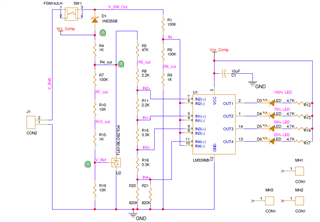
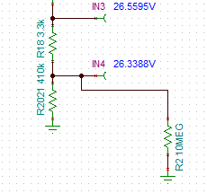
I am using LM339 IC for SOC Indicator, battery voltage is 52.4V to 53.5V

Objective is to show 25% ,50%,75% and 100 %

Attached Schematic and problem statement

25%,50% working fine but 75% and 100% are turn on at same time but when i touch using DMM probe it is working fine

what could be the problem?

Kindly help me to solve this Issue

  • I suspect that some input voltages exceed the valid common-mode range, which ends 2 V below VCC. What are the VCC and IN2+/− voltages?

    If this is the problem, you have to use comparators with rail-to-rail inputs. For supplies not above 5 V, use the LM339LV, otherwise, the TLV1824.

  • IN2+  26.856 Volts

    IN2-   26.857  volts.

    Vcc is 33V,output of comparator is low,which is driving the LED ON but it is happening while i probe only

    Thank you

  • This is not a problem related to the common-mode range.

    The IN2+/IN2− voltages are the same (within the 5 mV offset), so it is OK that the comparator switches. (The DMM has a finite input impedance, so it will affect the voltage by a little bit.) How does it behave when the INx− voltage is above IN1+ but below IN2+?

  • Exactly what node are you probing?

    It looks like you are probing the LED (on the output side or the VCC_COMP side?).

    Just remember that your meter will impose a parallel 10Meg load to what ever point you are probing. Depending on where you are probing, it could shift the voltage levels.

    Your thresholds are very close together - a little shift can make a big difference.

    If you probe the IN- node, the meter will cause a 140mV drop due to the extra 10M load - so you will be reading low.

    There is also a similar effect when probing the divider string:

    So be careful probing. Know your loading.

    Note that some "high impedance" DMM's (34401's) kick into 10M impedance when over 20V.

  • Thank you,i am using Fluke DMM

    i am probing at IC Comparator output side which directly connected to 10 meg ohm.

    i have done 10 nos,out of 10 ,4 board behave like this remaining boards were working fine

  • This is strange - probing the output should not affect the inputs. For the LED to light, the output must be low.

    I am assuming you are probing between GND and the pin 2 (Out1).

    Placing the 10M impedance across the "low" output, which is the equivalent of a few ohms to ground, should not make any difference. That is just not enough current to change anything.

    What exact model (85?) DMM are you using? What range? Can you provide another video showing the DMM display and front panel connections?

    What if you compare the voltages between a working board and a "misbehaving" board? Particularly each of the divider taps, outputs, R4_OUT and VCC_COMP. What are the voltages on each side of the LED when it is on (to find the current).

    Does VCC_COMP sag when all the LED's are on? Assuming ~5mA per LED, that is a 20mA swing in supply current. The Zener may not be regulating well.

  • Dear Paul,

    The issue is with Layout we guess,since 6 boards working fine,4 only issue 

    Yes as you mentioned Zener voltage is not maintained well, anyhow zener voltage is within mV variation, Thanks for your support and guidance over time

    Thank you

    venkatesh

  • Venkatesh,

    There can be a lot of shunt current change in TL431B, so this voltage reference may not be a flat as you might expect. The number of LEDs on competes for shunt current supply.  Relacing D1 with a device like LM317L floating regulator may improve performance. 

    Other potential improvements against noise, add capacitors to ground at IN2+ & IN- nodes.

  • Thanks sure i will do it

    suggest capacitor values since these are signals,may i use nF MLCC ?

    correct me if i am wrong

  • Venkatesh,

    Those caps should be fine. 

  • Thanks Ron Michallick