Other Parts Discussed in Thread: OPA858
Tool/software:
Title: Op-Amp Behavior Differences After Repeated Use: Could It Be Soldering or PCB Material Issues?
Hello Team,
I am facing an issue with two identical buffer circuit boards, and I’m trying to understand why their performance differs. I suspect it might be related to either the handling/soldering process or PCB material. Here are the details:
Setup:
- Both boards are configured as simple buffers (non-inverting unity gain).
- Input and output are connected to an SMU for testing ( giving voltage as input and for taking output).
- both operated at supply voltages(+5V and 0)
- only opamp soldered on board and nothing else component soldered.


Observations:
- Board 1(where R25 R24 resistors are there ):
- The bias current and offset voltage values are as per the datasheet during initial testing.
- After 2-3 experiments, the quiescent current from the supply exceeds the datasheet limits, indicating possible damage.
- If the op-amp is replaced, it starts working fine again, with values matching the datasheet.
- Board 2:
- The bias current and offset voltage values are much higher than the datasheet values from the start.
- After 2-3 experiments, this op-amp also starts pushing a lot of quiescent current beyond the specified limits.
- Replacing the op-amp is giving the results as buffer but the values are not as per datasheet ; it stays the same.
Questions:
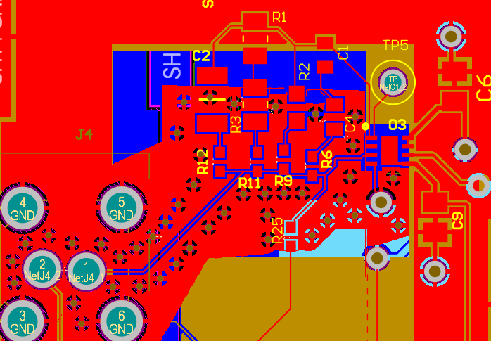
- Why does one board have values as per the datasheet and the other does not? Could this be due to soldering issues, handling during assembly, or PCB material differences(one board made of FR4 and one board made of Rogers)?
- I’m wondering if the PCB material (ROGERS vs. FR4) might be influencing the op-amp's performance. Could material differences be causing inconsistencies in offset voltage or bias current?
- Why does the op-amp start drawing excessive quiescent current after a few experiments on both boards?
- Could this be a result of thermal or electrical overstress during testing?
- Is it possible that damage occurs in the op-amp after several cycles, or is the op-amp being exposed to conditions outside of its safe operating range, even if it works fine initially?
Below are the test results from both boards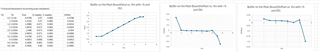 2nd board result:
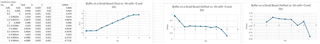
First board result

Could this behavior be due to handling or soldering issues?if soldering might be the issue can you please tell me what precautions to take care(Temperature etc). For example, is the op-amp being damaged during assembly or subsequent handling? while handling i am making sure of ESD protection.
so can you please help me where it is going wrong in simple buffer mode?


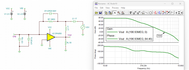
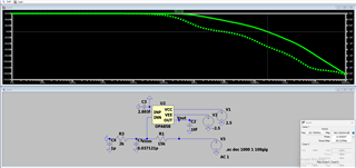
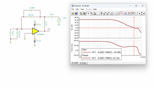
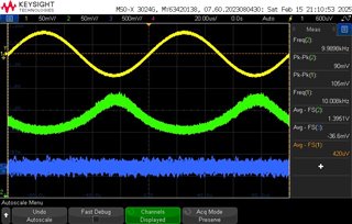 so yellow color graph is input which i gave from function generator , green color graph is the output of teh opamp where the sc is 1.36 .. and please ignore blue color graph , and the circuit layout diagram is attached