


Tool/software:
Hello, I recently started learning about analog circuits, and I am currently designing a simple photodiode amplifier circuit.
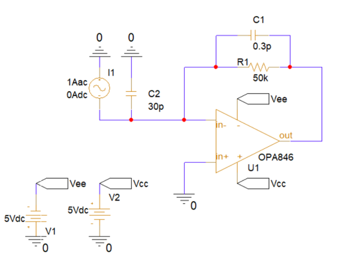
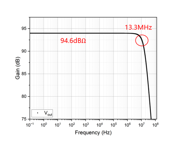
The photodiode has a parasitic capacitance of approximately 20pF, and I estimated the op-amp's parasitic capacitance to be around 10pF. I selected a feedback resistor of 50kΩ and a feedback capacitor of 0.3pF, allowing me to design a TIA circuit with a bandwidth of approximately 13MHz.
The OPA846 datasheet states that the differential mode input impedance is approximately 6.6kΩ, but my feedback resistor is 50kΩ, which is nearly 10 times larger. Would this cause signal distortion?
If I apply the voltage divider effect, I estimate that the signal could be attenuated by around -20dB. If my calculation is incorrect, please let me know.
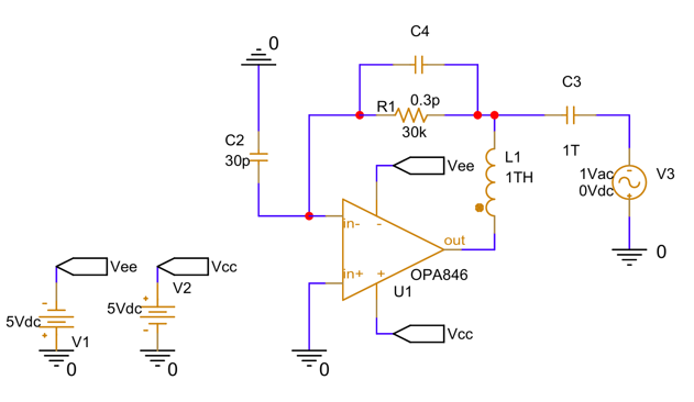
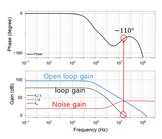
To investigate the phase margin, I added an inductor and a capacitor to the circuit and performed a simulation.
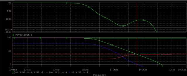
This is my first time analyzing the phase margin. I am wondering if I have properly marked the probe to investigate the phase margin. I would appreciate any insights or corrections to my understanding. Thank you!

 (please ignore the supply warning)