This thread has been locked.

If you have a related question, please click the "Ask a related question" button in the top right corner. The newly created question will be automatically linked to this question.

OPA548: 2x Current boost circuit

Part Number: OPA548
Other Parts Discussed in Thread: TPSM63610, OPA549, , OPA541, OPA593

Tool/software:

Hi,

Our customer is currently using an OPA548T in a constant current circuit to drive LD.

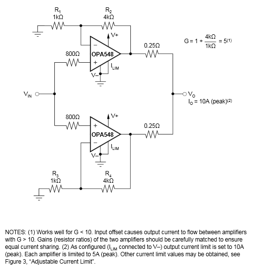
Now they need to design a new 5A constant current circuit, and are considering connecting the output of this circuit in parallel to double the current.

Are there any application notes that can be used as reference?

The existing circuit is also cooled with a large heat sink.

Could you please give us some advice if there are any problems with doubling the current by using AMPs in parallel?

Best regards,
Hiroshi


  • After checking with the customer for details, they told me that they plan to eventually combine the TPSM63610 and an OPAMP to configure a CV/CC circuit.

    Therefore, this parallel connection is only for testing the new LD.

    I think there will probably be no problem if the output is connected through a series resistor, but if you have any concerns, please let me know.

  • Figure 36 shows an example:

    Alternatively, configure the second amp as a voltage follower at the first one's output (this still needs series resistors).

  • Hi, Hiroshi-san

    Please use the diagram Clemens has included. This is one of the correct ways to implement a parallel power amplifier. One of the disadvantages of this particular circuit is that our input (Vin) is setting the vout for the op amp rather than the output voltage at the load. We can easily change this however to compensate for the voltage at the load. 

    Note, Parallel amplifiers will always have an inherent drawback in terms of forcing a power drop across the balancing resistors (.25 Ohm above). Additionally, in certain cases you may have one amplifier fight the other due to lack stability or too small of a balance resistor. 

    In most cases I find it easier to use a higher power amplifier, but it is certainly possible to parallel the OPA548. If the customer wants to upgrade to a higher current drive amp, OPA541 or OPA549 would do the trick. 

    We have this Application brief which cover parallel connection for power amplifiers here: Paralleling the OPA593 High-Voltage, High-Current Op Amp for 2 × Output Current

    The OPA593 device is far too weak to realize the 5A required, but the theory and parallel design considerations hold true for larger power amps like the OPA548. 

    If I were designing the circuit, I would probably take the easy road and just use the OPA549 for this function. If it is not possible to qualify a new part, then a parallel design would be fine as well. 

    I would be happy to create a simulation for the customer if they would like. I just need the transfer function for the constant current source (assuming this is an adjustable current source), the supply voltage used in the application, and any other details from the existing circuit design. 

    Please let me know if you have any questions. 

    Best,

    Jacob

  • Clemens-san, Jacob-san,

    Thank you for your detailed answer.
    I apologize for asking a question without checking the D/S circuit example.

    This customer is using many OPA548Ts as drivers for LD light sources in their existing system.
    Since multiple OPA548Ts are installed on a single PCB, the heat sink is also large.

    The new design requires even higher current.
    They will first evaluate the LD with a 2xBoost circuit.
    However, since this will generate more heat, they will also evaluate a CV/CC circuit with a DC/DC (TPSM63610) + OPAMP combination in parallel.
    If this does not work, they will also consider the OPA549.

    Best regards,
    Hiroshi


  • Thank you for supporting this customer Hiroshi-san. 

    Please let us know if you need any additional support from our side. 

    Thanks,

    Jacob