This thread has been locked.

If you have a related question, please click the "Ask a related question" button in the top right corner. The newly created question will be automatically linked to this question.

INA122: Sense current from an electrolytic cell with potential difference ranging from 300mV to 700mV

Part Number: INA122
Other Parts Discussed in Thread: INA326, , INA114, INA500, PSPICE-FOR-TI, INA121, INA118, INA128, TL7660

Tool/software:

Hello

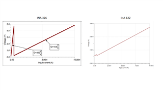
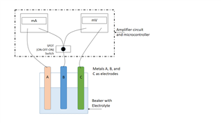
I am trying to figure out a way to measure current from an electrolytic cell. The potential difference (as measured by the voltmeter) between its electrodes ranges from 300mV to 700mV. If the currents are measured using a shunt resistor of 2.5 ohms, they are in the range of 0.2mA to 5mA. I would like to design a circuit for measuring these currents. I was planning to use INA326 based current sensing.

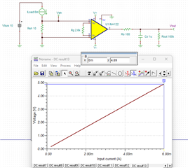
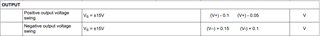
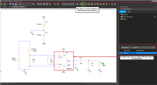
But due to the INA326 unavailability, I was considering to use INA122 as an alternative as stated in the page no.12 in the modifications section of the reference design document. Unfortunately, I am unable to get the results similar to those obtained for INA326. Please let me know, what changes should I make to the design to get similar DC characteristics. Also, I would like to know if there are any other circuits that I can use instead for my application.

Thank you. 

  • Hi Durgesh, 

    Welcome to E2E! Could you clarify how you set up the INA122 and if it was in simulation or in circuit tests? What were the results you are expecting and how did the INA122 perform? 

    Thank you!
    Regards,
    Ashley

  • Thank you for the quick response!
    This was in a simulation. I simply replaced the INA326 with INA122 in the circuit (attached) and checked the DC characteristics (attached).
    I was expecting the INA122 to have similar gain characteristics as INA326 - that is, two significantly different gain values for different ranges of currents. 
    Regardless, the gain value of INA122 is quite high, so I may do away with the switching circuit altogether. I'm still wondering if it is suitable for the battery current sensing application that I previously mentioned. 


  • Hi Durgesh, 

    The INA122 and INA326 are different devices that require a different setup for proper implementation. The INA122 pin 5 is a reference pin as opposed to the iNA326 that uses an additional resistor pin to set the gain. As a result, the INA122 cannot just be pin-to-pin replaced with the INA326 and expect similar performance. The switching circuit will not impact the gain as the INA326 circuit did. 

    Could you clarify if you are also using the device in 5V supply and what gain you are trying to use? What is the output range you are trying to achieve? 

    Regards,
    Ashley

  • Thank you for explaining this.

    Let me elaborate my use case. 
    I have an electrolytic cell that outputs a voltage that ranges anywhere from 300mV to 700 mV between its electrodes. I have been measuring the current from this cell using a 10 ohm sense resistor and it ranges from 6mA to 0.2mA. I want to measure both the voltage (between the electrodes) and current (through the sense resistor) using a microcontroller (Arduino/MSP430). Unfortunately, I am unable to do so in the case of the current due to its small value. Thus, I was looking for an amplifier circuit that could "sense" this current and output a voltage in the range of 0 to 5 V (which is detectable by the microcontroller) so that I could at least get a current resolution of 0.1mA.

  • Hi Durgesh, 

    Thank you for the additional information on your application. The INA122 can be used for your current sensing application, but you will have to change the gain resistor in order to amplify the input signal of 300mV to 700mV, using the device with a supply voltage of +5V and ground, with Vref of 0V. Based on my calculations, a gain of around 70 to 80 should be enough depending on how much headroom you would like. This would translate to a gain resistor of 2.84kohms or 2.67kohms.

    Please note that you cannot get all the way to 5V on the output using a 5V positive supply rail. The output will swing 100mV to the rail, so you will need to set the range to 0 to 4.9V for your microcontroller. 

    INA122 output swing specification: 

    For the voltage, are you also in need for a device to voltage sense the battery? 

    Regards,
    Ashley

  • That's great! As a novice in this domain, this is extremely helpful. Thank you. 

    Yes I am going to need a device to voltage sense the battery. In fact, my next step is to build a device that measures current and voltage of an electrolytic cell using a three electrode system (picture attached), switching between the two pairs of electrodes while disconnecting the third one. 


    Another query: Where I am located, I am often faced with unavailability of components, especially ICs. Is there any hard and fast way to quickly compare (like you did) between two INAs/OPamps in the TINA simulation? Suppose I want to compare the DC characteristics of INA122 and INA114 etc. I am not adamant about using INA122, if you think there is any other INA that could do the job, please recommend.

    Thanks again for your timely help. 

  • Hi Durgesh, 

    I understand your concern regarding alternate solutions for your system. I will work on a solution that fits your application needs and respond back to this post with my recommendations tomorrow. 

    Thank you!
    Regards,
    Ashley

  • Hi Durgesh, 

    There are a few key specs to keep in mind when choosing an INA to fit your solution. The INA122 and INA326 are more specialized INAs that are difficult to find pin-to-pin replacements for without having to modify gain resistors and changing the circuit. To make a current sensing circuit compatible with a wider range of our portfolio, it is recommended to use a dual supply instead in order for the INA to be in linear operating range or a reference voltage would have to be applied. For the design below, I adjusted the supply voltage and gain resistor to fit the above design requirements listed. 

    I created a PSpice schematic to help easily compare behavior across different INAs. I set the supply voltage range to be +/-15V (30V total). If you need your output to go closer to 5V, having a higher supply voltage would help to ensure this.

    low-side-current-sensing-2025-02-13T21-48.zip

    Some pin-to-pin alternative INAs that I found are below: 

    INA828 data sheet, product information and support | TI.com

    INA818 data sheet, product information and support | TI.com

    INA121 data sheet, product information and support | TI.com

    For your voltage sensing circuit, we also have INA500 (INA500 data sheet, product information and support | TI.com) that is suitable for battery test voltage monitoring circuits. This device is an integrated difference amplifier. 

    If there are other specific design requirements that are needed, please let me know and I can help with the design further. 

    Thank you!
    Regards,
    Ashley

  • Thanks a ton! That's a lot of effort.

    Unfortunately, I do not have PSpice to explore the above schematic, but I think I can check this in TINA as well, right? I only mentioned the 0-5V output range as I wanted it to be connected to the microcontroller. 0-3.3V would suffice too. I am making this device to be portable, hence battery operated, so 30V supply voltage is not feasible. Also I am looking for DIP-8 based packaging for the ICs- INA121P fits, but it too requires a dual supply.
    To summarize, the hard constraints are:
    1. Must be able to sense current from 6mA to 0.2mA.
    2. Should output a voltage that could be detected by a microcontroller (MSP430/Arduino) and get a 0.1mA current resolution.
    3. Should not have a dual-supply requirement.
    4. Should be available in a DIP-8 packaging.

    Thank you

  • Hi Durgesh, 

    We have PSpice-for-TI available for download on TI.com if you would like to use the PSpice simulation: PSPICE-FOR-TI Simulation tool | TI.com. The reason I offered a PSpice simulation is because it is flexible on replacing INA devices in the circuit with the integrated PSpice part search. You can still use a TINA schematic but in order to simulate the DC behavior, you will need to manually download the model from the product pages and import the macro. 

    With the design requirements you have listed, it is unfortunately not feasible to be able to accommodate all of them. I've listed two potential design options but it will require some compromise on your requirements: 

    Option 1: If you are able to create a dual-supply rail, items 1,2, and 4 can be designed with either 3.3 or 5V output requirement. Using a 9V battery for the positive power supply, and a negative 5V rail (this can be adjusted - was used as an example), the attached TINA schematic is to help simulate this circuit. For a 3.3V output range, a gain of 55 is set and the expected output from the INA would be from 110mV to 3.3V. For a 5V output range, a gain of 83 is set and the expected output from the INA would be 166mV to 4.98V. 

    durgesh_low_side_sensing_e2e.TSC

    We have 4 INAs in our portfolio in DIP-8 that can fit this requirement. Please see this link for the device comparison table (INA121, INA128, INA118, INA114): Comparison table

    Option 2: If the package can be changed to an SOIC-8, we have current-sensing amplifiers that are suitable for this application that can meet items 1,2, and 3. The specific selection of current sense amplifier would be taken care of by a different team, but if you would like this solution, we can route this thread to their team. 

    Please let me know if you have any questions.
    Thank you!

    Regards,
    Ashley

  • Thank you so much!

    Option 1 seems plausible to implement for my application. I suppose a voltage converter like TL7660 could be used to get the negative rail. I will probably have to use two 9 V batteries and provide a ±9V supply. 

    Thanks again! For a novice like me, this discussion has proven quite insightful. Makes me confident to build more devices for several other applications if such thorough and professional guidance is readily available. 

    Thank you

    Slight smile

  • Hi Durgesh, 

    Happy to help! Slight smile

    For the voltage regulator, I recommend consulting with the switching regulator team that can help to recommend appropriate parts. If you would like to go this route, please feel free to start a new thread or we can re-direct this one. 

    Regards,
    Ashley

  • Yes please. That'll be great!

  • Hi Durgesh, 

    I have transferred this thread to the appropriate team. 

    Thanks,
    Ashley