This thread has been locked.

If you have a related question, please click the "Ask a related question" button in the top right corner. The newly created question will be automatically linked to this question.

INA241B: current sensing wrong

Part Number: INA241B
Other Parts Discussed in Thread: INA241A, INA240

Tool/software:

Hi team,

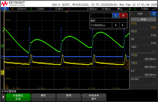
My customer is using INA241B for solar inverter high-side current sensing. But in test waveforms, INA241 output can follow actual current change at the beginning of cycle begin, but can't follow afterwards and turn down.

Pls help check what's wrong and how to fix it?
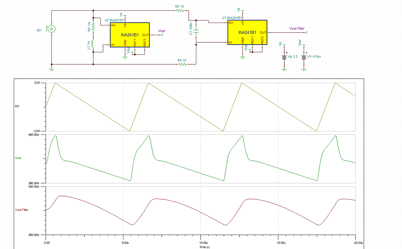
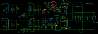
SCH:

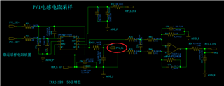
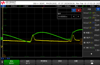
Waveforms (yellow: PV1_IL, connected to INA241 OUT; Green: actual IL ; Blue: DRV1_L, drive signal. All circled in red above)

Thanks,

Severi

  • Hello Severi,

    I believe it is the inductance of the Rshunt that is causing the issue.  Have them change C68.  I assumed the inductance was about 1nH for the Rshunt they have populated but that is a guess.  The value of the I have is 100nF as seen in the simulations below.  The simulation below is an example without the filter and one with capacitor.  They currently have 100pF on C68 and that will need to increase.  This value will be dependent on the inductance of the Rshunt and the layout.

    Rshunt_inducance_INA241B.TSC

  • Hi Javier,

    Thank you for your suggestion, we tried higher capacitor, it can work normally with low current. Rshunt=1mohm.

    But when current become higher, there will be output clipping and ringing. Below are waveforms:

    C68=33nF, I=21A max C68=47nF, I=21A max

    And customer didn't try higher capacitor like 100nF, because higher capacitor brings more delay, they can't accept it.

    Pls help check below questions:

    1. Why Rshunt inductance will cause sense can't follow and how capacitor fix it? And how to select a suitable capacitor according to inductance or other spec?

    2. How to fix new clipping and ringing problem, since customer can't accept capacitor over 47nF? And pls explain the reason of clipping and ringing.

    Thanks,

    Severi

  • Hello Severi,

    What is the VCM at the input.  I assumed it was 0V.  Could they measure the voltage at the input with respect to the INA241A GND.  If the VCM is changing the device will attempt to hold the output for about 1µs as stated in the datasheet.  The INA296 does not have this feature.  

    1. Why Rshunt inductance will cause sense can't follow and how capacitor fix it? And how to select a suitable capacitor according to inductance or other spec?

    The di/dt across the resistor will act like a voltage drop with respect to current.  If there is an inductance this will create a larger voltage change depending on the slew rate of the current.  It is best to match the RC filter to match this so that you see the correct voltage across the INA241

    2. How to fix new clipping and ringing problem, since customer can't accept capacitor over 47nF? And pls explain the reason of clipping and ringing.

    This could be the issue I mentioned above.  From the schematic above I cannot tell the VCM and the VCM transient expected at the device.  

    Figure 7-1 shows the INA241x PWM enhancement performance. When INA241x senses the large commonmode ΔV/Δt transients, the device holds the output for 1μs

  • Hi Javier,

    I think you're right. We try to optimize drive signals and it can decrease clipping and ringing. However the customer control frequency is higher than 125kHz, which is over INA241 rejection limit, so still can't totally fix it.

    Pls check below questions:

    1. What is the ΔV/Δt threshold will trigger INA241 hold output 1us?

    2. There is no hold output description in INA240 datasheet, only said rejection achieved by high CMRR. So is INA240 rejection feature different from INA241?

    3. Do we have better rejection selection than INA241, which can support over 125kHz?

    Thanks,

    Severi

  • Hello Severi

    1. What is the ΔV/Δt threshold will trigger INA241 hold output 1us?

    This in not specified and will vary but it needs to be about a 4V VCM change with a slew rate at about 100V/µs.

    2. There is no hold output description in INA240 datasheet, only said rejection achieved by high CMRR. So is INA240 rejection feature different from INA241?

    Yes it is different.  I think the INA241 may work better in most applications due to the speed.

    3. Do we have better rejection selection than INA241, which can support over 125kHz?

    At this moment we do not have something avalible.

    Regards,

    Javier