This thread has been locked.

If you have a related question, please click the "Ask a related question" button in the top right corner. The newly created question will be automatically linked to this question.

OPA858: opa858

Part Number: OPA858

Tool/software:

OPA858 Inverting Mode Output Distortion Asymmetry Issue

Body:

Hello,

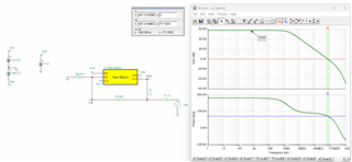
I am using the OPA858 in an inverting amplifier configuration with:

  • Rin = 100kΩ
  • Rf = 1MΩ
  • Non-inverting terminal grounded
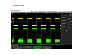
  • Input: 1 kHz square wave (shown in yellow)
  • Output: Measured in green (oscilloscope screenshot attached)

Issue:

The output signal shows asymmetrical distortion:

  • The top side of the output waveform has less distortion.
  • The bottom side of the waveform has more distortion.
  • The pulse width of the top and bottom halves is not the same, despite the input being a clean square wave.

  • Please specify the supply, input, and output voltage ranges.

  • 0 to 0.15V is  input range ,and supply is +-2.5V and here i gave input 100mV step input from function generator, with supply ranges 2.5,-2.5, the opamp is non rail to rail ,so output range is +1.5 to -1.5 .

  • Hi Saisankar,

    As this is one of our faster devices, Rf has a significant impact on the stability of the circuit. Could you adjust Rf to ~453 and Rg to ~45.3 and see if this is making a difference in the signal you are seeing?

    Best Regards,

    Ignacio

  • Hi Saisankar,

    As Ignacio mentioned, high Rf can have significant impact on stability of the circuit. Please try to use less Rf value with the same gain of 10x.

    I simulated your circuit, and got a phase margin of only 4 degrees, whereas, a phase margin of at least 45 degrees is required for system stability.

    After changing Rf and Rg, the system looks stable with sufficient phase margin.

    I have attached the TINA schematic below for your reference.

    Regards,

    Aditya Gosavi

    OPA858 inv config 1M Rf stability.TSC

  • I stabilized an OPA858 high-speed op-amp circuit. I added a 0.1 pF feedback capacitance and used a 1 MΩ feedback resistor to stabilize the phase margin, achieving 85 degrees. The circuit is now stable, but the frequency response isn't as expected. why the response is as attached .Isnt  this behavior expected when using high feedback resistance (in the MΩ range) , will the response be clear only for 100ohms of resistor .

    by adding 0.1pF capacitance phase margin is more , but the response is like what i attached , for 453 ohm and 45 ohm the response is fine there are no unsymmmetrical distortions like what is attached. 


  • Hi Saisankar,

    There were no attachments shared. However, adding the feedback capacitor, would affect your bandwidth as you will be creating a low-pass filter with this configuration and would affect the step response you see at the output and would not be as sharp. I am not sure if this is what you are referring to with the frequency response not being as expected.

    Best Regards,

    Ignacio