This thread has been locked.

If you have a related question, please click the "Ask a related question" button in the top right corner. The newly created question will be automatically linked to this question.

LM359: Urgent help, why is there such a loud noise?

Part Number: LM359

Tool/software:

Please help me
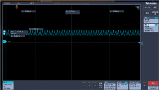
I designed a circuit diagram based on the LM359 op amp. After it was actually powered on, I found that the noise was very loud. Can you help me analyze the reason? Please, because of the time rush, this circuit made me very distressed. By the way, I provide specific information. (1)The LM359 is powered by a single 12V power supply.
(2) The oscilloscope shows the noise.
(3) After simply connecting the power supply, there is such a loud noise without any input signal.
So, I really can't find the reason.
Help! ! ! ! ! ! Please help me
  • Hi,

    Thank you for providing the information and images. It seems like the circuit is having stability issues. This device is a very unique device with a lot of moving parts to consider. However, there are some steps we can take to try to stabilize the circuit. One question is the addition of Rb2 and Rb1. Is there a reason these were added and does removing them change anything?  I was also curious if adding some feedback capacitors would help the stability at least to the first two stages. The datasheet highlights 1pF to 5pF feedback capacitors in parallel to the Rf resistor. I would start with trying these steps first to see if you see any change in the signal you are seeing.

    Best regards,

    Ignacio

  • Hello
    Mr. Ignacio
    First of all, thank you very much for your attention.
    First, I removed Rb1 and Rb2 as you said. But it didn't actually change the problem. The original function of Rb1 and Rb2 is to form a high-pass filter with the previous capacitor to remove some low-frequency signals.
    Second, some feedback capacitors can be added. After adding the 1pF to 5pF capacitor given in the data sheet, the output became very small during simulation, so I didn't add feedback capacitors.
    So, I really don't understand it now, please, please help me

    Primary school students who like electronics

  • Hi,

    The datasheet highlights the use of different compensation methods as a way to adjust the circuit. If it is possible to solder some feedback capacitors to the feedback resistors that would be a good debug step to try in the first two stages. In a non-inverting configuration, the device requires some form of external compensation. Is there a layout that can be shared, in general is the layout following high speed layout best practices?

    Best Regards,

    Ignacio