This thread has been locked.

If you have a related question, please click the "Ask a related question" button in the top right corner. The newly created question will be automatically linked to this question.

OPA836: Saturation Error

Part Number: OPA836


Tool/software:

Hello

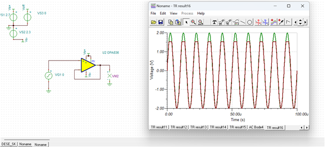
I'm simulating a design using two OPA836, the first one used as a difference amplifier, which feeds into a Sallen Key cell.

The output of the second stage saturates at a much lower value than the first stage, and much lower than the supply voltage.

This happens only on the positive swing, on the negative swing the sallen key output reaches correctly the negative supply voltage.

I tried simulating it both with Pspice and TINA TI, same result.

It shows the same behaviour also if I simulate just one OPA836 used as a buffer: if I place a series resistor in the input path, and this effect is mitigated if i place a resistor in the feedback path(gain stil remains 1)

I'm failing to explain it since, according to the datasheet, the input impedance should be quite high, so a series resistance should not have an impact.

In fact it seems that there's a current flowing into the OPAMP inputs that causes the voltage drop.

I also tried replicating it testing a real circuit but I didn't get the same behaviour.

Here's the simulation file

DESE_SK.TSC

Mattia

  • Hello Mattia,

      Your analysis is correct, the resistor should not make an impact due to high input impedance. I am looking into this issue, and get back to you in the next day.

    Thank you,
    Sima

  • Hello Sima,

    Thank you for your reply

    Have you got some new insights about this issue?

    Thanks again

    Mattia

  • Hello Mattia,

      I am sorry for the very long delay. Thank you for sharing the detailed debugging steps, I was able to replicate the same issues you were seeing. The reason the model is doing this, is because the input common-mode voltage of the amplifier is violated. This device is rail-to-rail output and input up to VS-, but there is about 1V headroom from VS+ needed. 

       Easiest way to see this is when used as a buffer as you mentioned in your debugging steps, it clamps only at VS+ because input common-mode voltage is violated at this supplies. I have VS+ set to 2.7V to match it to datasheet at VS+, and it clamps at around 1.53V which is around where input common-mode voltage is specified in datasheet of 1.5V min.

       In order to avoid this violation, you may set a voltage bias or redefine your voltage supplies. Let me know if you need assistance with that for your application.

    Thank you for checking in and your patience,
    Sima